29 30
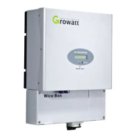
3.installation rubber pipe into the knock-out hole and pull the pipe nut slightly, feed
the cables through the pipe into the wire box till the terminal.
4.connect the PV cables to the terminal correct.
5.7 Commissioning Checking
Cover the wire box.
Close the DC separate unit and the DC switch on the inverter.
When the PV panels are connected and PV voltage is greater than 100 Vdc but
the AC grid is not yet connected, the message on the LCD display produce the
following messages in order: “Growatt Inverter”-> “Waiting” -> “No AC
connection”. The display repeats “No AC connection” and the LED will be red.
Setting grid model choice. See the chapter 6.2 “Setting the LCD display”.
Close the AC separate unit between inverter and grid. The normal operating
sequence begins.
Under normal operating conditions the LCD displays “Power: xxxx.xW”. That is
the power fed to the grid. The LED turns green.
This completes the check.
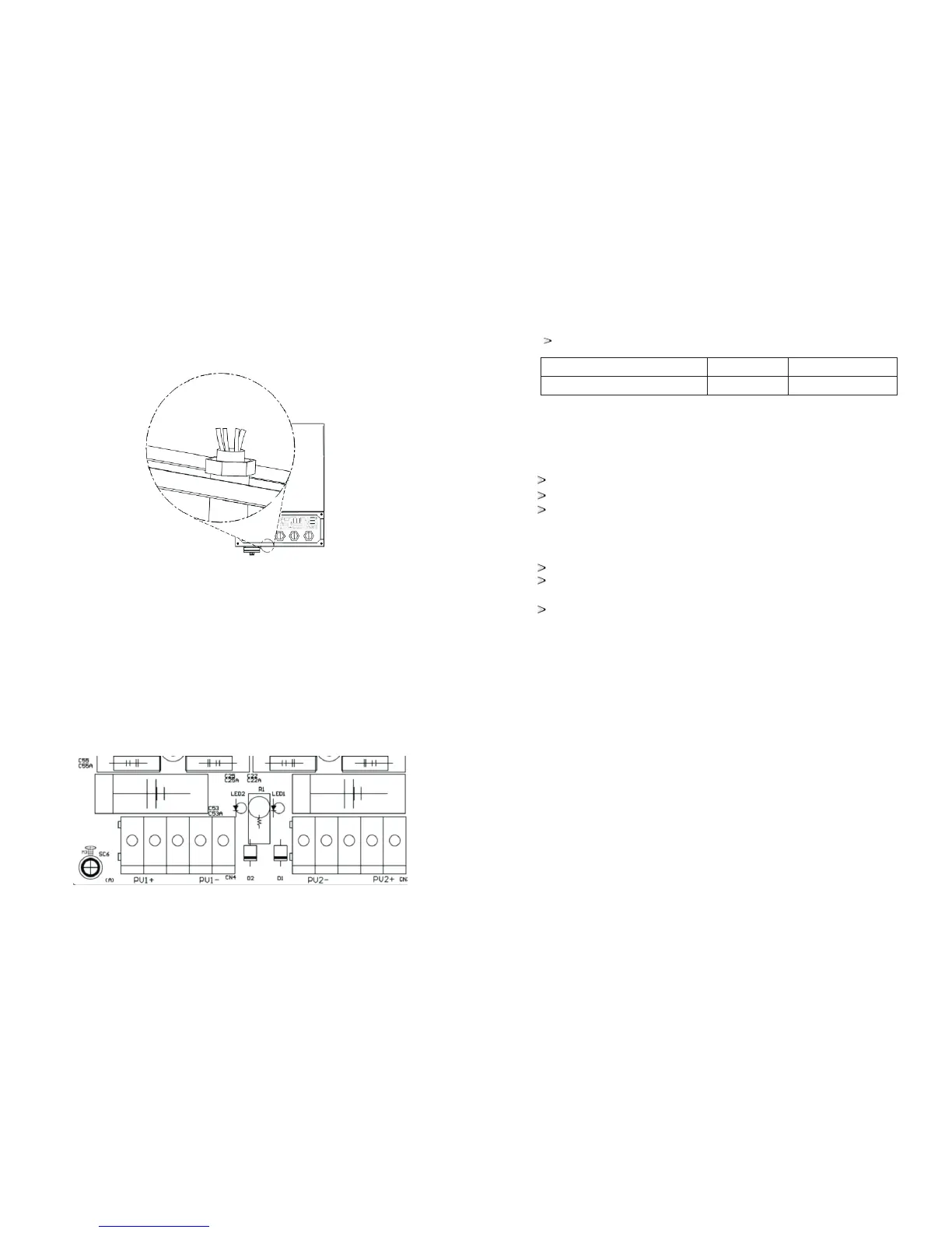
5.Checking the wiring of PV positive and cathode connect is right then turn on DC
switch.
NOTE:
When DC switch turn off, PV wiring mistake the wire Box board LED light brighten.
Cable requirements:
Product Model
GROWATT 1.5K/2K/3K-US
Area(mm²)
3.30~5.26
AWG No.
10~12