20 / 28
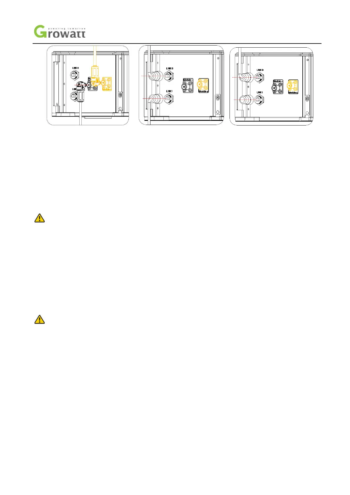
Figure 19: ARK 2.5H-A1 Electrical wiring connection diagram
Step 1: Insert the power cable into the corresponding port, then there is click sound indicating the connection is ok.
Step 2: Insert the communication cable into the "Link0" and "Link1" port, and then tighten the communication terminal clockwise.
(“
Link0” connects to “Link1” of the previous module. For the battery adjacent to the high voltage controller, "link0" is connected to
the "BMU" of the high voltage controller. “Link1” connects to “Link0” of the next module.)
Step 3: Insert a plug into the "Link1" port of the last battery module. The plug is an annex of HVC 60050-A1 (high voltage controller).
Step 4:
Connect to adjacent battery pack using a 6mm2 grounding wire through grounding terminal.
Notice
The battery module furthest from the HVC 60050-A1(high voltage controller) is defined as the last battery module.
Please pay attention to the connector color when connecting the power line. Only the same color of the connector could be
connected together.
The power lines between the battery modules are connected in series. Be careful not to short-circuit the battery modules during
the connection process.
5. Power on/off Battery system
Notice
The installation and use of batteries need to be operated by professional technicians.
Do not contact any positions with potential difference.
Prohibition sign should be hung on the battery: " Non - professionals, do not touch.
If any abnormalities occur during the startup phase, power off the system immediately. After problem confirmed, proceed
again.
Make sure the inverter is turned off before checking the battery system.
 Loading...