Danger
Warning
16
15
Inverter wiring 6
6.1 Security
There may be a high voltage in the conductive part of the inverter,
which may cause electric shock.Therefore, when installing the
inverter,make sure that the AC and DC sides of the inverter are
powered off.
Static electricity may damage the electronic components of the
inverter.Anti-static measures should be taken during the
replacement or installation of the inverter.
Moisture and dust penetration can damage the inverter
Ø Make sure that the waterproof cable gland is firmly tightened.
Ø If the cable connector is not installed correctly, the inverter
may be damaged due to the penetration of moisture and dust. All
warranty claims are void
Note
6.2 AC side wiring
Before making electrical connections, please make sure that the
DC switch of the inverter is in the "OFF" state and disconnect the
AC side MCB, otherwise the high voltage of the inverter may
cause death.
Ø Each inverter must be installed with an AC circuit breaker
independently, and it is forbidden to share multiple inverters.
Ø It is forbidden to use single-core wire at the output terminal of
the inverter.
Ø It is forbidden to use aluminum wires as output cables.
Ø Please ensure that the output cable is well connected
before turning on the inverter.Ignoring the above warning
may damage the machine or cause other losses.In this case,
the company reserves the right not to carry out the warranty
and bear any responsibility and related expenses.
Moisture and dust penetration can damage the inverter.
Ø Make sure the cable connector is securely tightened.
Ø If the cable connector is not installed correctly, the inverter
may be damaged by moisture and dust. All warranty claims are
invalid.
Danger
Warning
Note
Residual current protection device (RCMU)
Because the inverter itself has a high-precision residual current detection device,it is
not recommended to install a leakage protection switch in the system.If for some
special reason,it must be installed between the inverter output and the grid.Please
install a type B leakage protection switch above 300mA.When multiple leakage
protection switches are installed in the system,it is forbidden to share the neutral
line,otherwise the leakage protection function may be triggered by mistake and
cause the switch to trip.
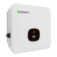
Fig 5.9 Schematic diagram of inverter wall mounting
 Loading...