Communication Connection
Please use supplied communication cable to connect to inverter and PC. Follow on-screen instruction to
install the monitoring software. For the detailed software operation, please check user manual of
software. The monitoring software is downloadable from our website www.ginverter.com.
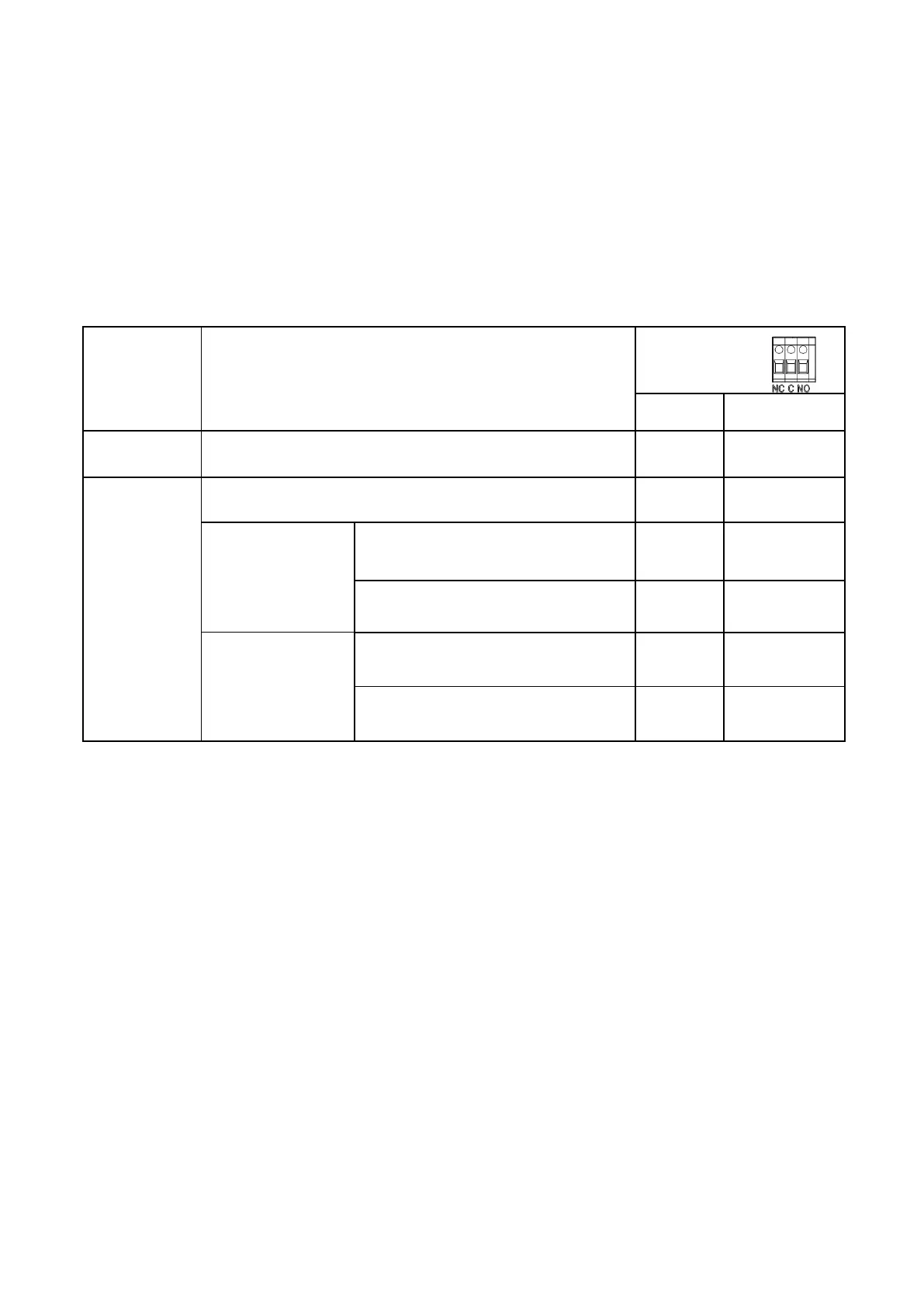
Dry Contact Signal
There is one dry contact (3A/250VAC) available on the rear panel. It could be used to deliver signal to
generator when battery voltage reaches warning level.
Unit is off and no output is powered.
Output is off and no output is powered
Battery voltage <
Low DC Cut-off Voltage +2Vdc
Detected there‟s AC input
Battery SOC <
Low DC Cut-off Soc+5%
Detected there‟s AC input
Electrical Performance
Inverting
Overload Capacity
1. For 100%<Load<120%, Fault (Power off) after 10 seconds.
2. For 120%<Load≤300%, Fault (Power off) after the 5 seconds.
Soft Start in Inverter Mode
When the inverter is turned on, the output voltage gradually ramps up from 0VAC to rated voltage in about 1.2
sec. This effectively reduces otherwise very high starting inrush current drawn by AC loads such as Switched
Mode Power Supplies and inductive loads. This will result in lower motor inrush current, which means less
impact on the loads and inverter.
Caution:
After the inverter is switched on, it takes a finite amount of time to self-diagnose and get ready to deliver full
power. Always switch on the load(s) after a few seconds of switching on the inverter. Avoid switching on the
inverter with the load already switched on. This may prematurely trigger the overload protection. When a load
is switched on, it may require an initial higher power surge to start. If multiple loads are being powered, they
should be switched on individually so that the inverter is not overloaded by the higher starting surge.
 Loading...