4
CONTENTS
Page
1. General description 4
1.1 Applications 4
1.2 Operating conditions 4
1.3 Sound pressure level 4
2. Safety 4
3. Transportation and storage 4
4. Installation 4
4.1 Submerged installation on auto-coupling 5
4.2 Free-standing submerged installation 5
4.3 Dry installation 5
4.4 Level controllers 5
4.5 Temperature sensors 5
4.6 Moisture sensors 5
5. Electrical connection 6
5.1 Motor protection 6
6. Start-up 6
6.1 Checking of direction of rotation 6
7. Maintenance and service 6
7.1 Service kits 7
7.2 Contaminated pumps 7
8. Fault finding chart 8
9. Disposal 8
Before beginning installation procedures, these in-
stallation and operating instructions should be stud-
ied carefully. The installation and operation should
also be in accordance with local regulations and ac-
cepted codes of good practice.
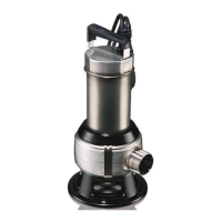
1. General description
1.1 Applications
GRUNDFOS AP80 pumps with vortex impeller are designed for
pumping:
• raw sewage,
• wastewater,
• wastewater with high concentration of fibrous material.
The pumps are designed to pump the above liquids in places
such as:
• public buildings
•blocks of flats
• factories/industry
• garages
• underground car-parks
• car wash areas
• restaurants
• hotels
The compact design makes the pumps suitable for both sub-
merged and dry permanent installation (dry installation applies
only to pumps of 4.8 kW and up). In the case of submerged instal-
lation, the pumps can be installed by means of an auto-coupling
guide rail system or they can be provided with a separate base
stand for free-standing installation.
When fitted with a base stand and a flexible discharge hose, the
pumps can also be used for temporary installations (as standby
pumps) and can be moved from one installation to the other by
means of the handle, lifting eye bolts or hole of the motor.
In the case of dry installation, the pump is supplied with a cooling
jacket for internal or external cooling of the motor (dry installation
applies only to pumps of 4.8 kW and up).
The AP80 pumps are designed with a free spherical impeller
clearance of 80 mm.
1.1.1 Potentially explosive environments
Use the explosion-proof AP pump versions for applications in-
volving the risk of explosion.
Note: The explosion classification of the pump is EEx de IIB T4
and must in each individual case be approved by the local au-
thorities for use at the desired installation site.
Note: The separate motor starter/control box in standard version
must not be installed in potentially explosive environments.
1.2 Operating conditions
1.2.1 pH Value
AP pumps in permanent installations can be used for pumping liq-
uids with a pH value between 4 and 10.
1.2.2 Liquid temperature - submerged installation
Liquid temperature: 0°C to +40°C.
For short periods up to +60°C.
1.2.3 Liquid temperature - with cooling jacket
Liquid temperature: 0°C to +40°C.
For short periods up to +60°C.
1.2.4 Density of pumped liquid
Maximum density of pumped liquid: 1100 kg/m³.
1.2.5 Level of pumped liquid
In the case of submerged pump installation, the lowest stop level
must always be above the top of the pump housing.
1.2.6 Operation
Maximum 20 starts per hour at intermittent operation.
Note: At continuous operation for more than one hour at a time, a
cooling jacket must be installed if the motor is not completely sub-
merged during operation.
1.3 Sound pressure level
The sound pressure level of the pump is lower than the limiting
values stated in the EC Council Directive 98/37/EEC relating to
machinery.
2. Safety
3. Transportation and storage
To ensure proper support during transportation, the pump is se-
cured inside a sturdy carton when delivered from the factory. As a
safety precaution, the carton must not be removed until the pump
is to be installed.
Make sure that the pump cannot roll or fall over.
Always lift the pump by means of the handle, lifting eye bolts or
hole, never by means of the motor cable or the hose/pipe.
For long periods of storage, the pump must be protected against
moisture and heat.
After a long period of storage, the pump should be inspected be-
fore it is put into operation. Make sure that the impeller can rotate
freely. Pay special attention to the condition of the shaft seals and
the cable entry.
4. Installation
See mounting dimensions at the end of these instructions.
The loose nameplate supplied with the pump should be fixed at
the installation site.
Prior to installation, check the oil level in the oil chamber, see
section 7. Maintenance and service.
Pump installation in wells must be carried out by spe-
cially trained persons.