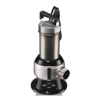
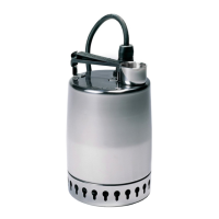
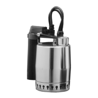
The GRUNDFOS UNILIFT AP12, AP35, AP50 is a single-stage submersible pump designed for pumping wastewater. This manual provides installation and operating instructions for these models.
Function Description
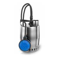
The UNILIFT AP pump is intended for pumping wastewater that may contain a limited quantity of solids, without causing blockages or damage to the pump. It can be used for both automatic and manual operation and can be installed permanently or used as a portable pump.
Applications include:
- Drainage of flooded cellars or buildings.
- Groundwater lowering.
- Pumping of water from drain water collecting pits.
- Pumping of water from surface water pits with inflow from roof gutters, shafts, tunnels, etc.
- Emptying and filling of swimming pools, ponds, pits, etc.
- Pumping of fibre-containing wastewater from laundries and light industries.
- Pumping of domestic wastewater from septic tanks and sludge treating systems.
- Pumping of domestic wastewater without discharge from water closets.
Incorrect application, such as pumping liquids that block or wear the pump, is not covered by the warranty. The pump is not suitable for sewage, liquids containing long fibres, flammable liquids (oil, petrol, etc.), aggressive liquids, or liquids containing solids exceeding the pump's recommended maximum particle size.
Important Technical Specifications
General:
- Storage temperature: Down to -30 °C.
- Minimum liquid temperature: 0 °C.
- Maximum liquid temperature: +55 °C continuously. For UNILIFT AP12, AP35, and AP50 without a float switch, where the media cannot touch the cable and the plug, it can handle up to +70 °C for 30 minutes, for time periods below 3 minutes.
- Installation depth: Maximum 10 m below liquid level.
- pH value: 4-10.
- Density: Maximum 1100 kg/m³.
- Viscosity: Maximum 10 mm²/s.
- Sound pressure level: Lower than the limiting values stated in EC Council Directive 2006/42/EC.
Particle Size:
- UNILIFT AP12: Max. spherical diameter 12 mm.
- UNILIFT AP35: Max. spherical diameter 35 mm.
- UNILIFT AP50: Max. spherical diameter 50 mm.
Electrical Connection:
- The pump must be suitable for the supply voltage and frequency available at the installation site, as marked on the nameplate.
- Must be connected to an external main switch (lockable type if not installed close to the switch).
- Three-phase pumps require an external motor-protective circuit breaker with differential release, corresponding to the pump nameplate's electrical data. If a level switch is connected, the motor-protective circuit breaker must be magnetically operated.
- Single-phase pumps have thermal overload protection and do not require additional motor protection; they stop automatically when overloaded and restart after cooling.
- Installations must be fitted with a residual-current device (RCD) with a tripping current less than 30 mA.
- The power supply plug must comply with local regulations and have the same protective earth (PE) connection system as the power outlet.
- Power cables without a plug must be connected to a supply disconnecting device incorporated in the fixed wiring according to local rules.
Usage Features
Installation:
- Location: Always ensure at least 3 m of free cable above the liquid level. This limits installation depth to 7 m for pumps with 10 m cable and 2 m for pumps with 5 m cable.
- Minimum Space: The pit, basin, or tank must be sized according to the water flow and pump performance. For permanent installations with a float switch, minimum dimensions are 550 mm (width) x 600 mm (height), with the float switch set to minimum free cable length.
- Foundation: Place the pump on a plate or bricks to keep the inlet strainer free of sludge, mud, or similar materials.
- Lifting: Lift the pump using its handle. Do not lift by the power cable, outlet pipe, or hose. For well or tank installations, use a wire or chain fastened to the pump handle.
- Positioning: The pump can be used vertically or horizontally, with the outlet as the highest point. The inlet strainer must always be completely covered by the pumped liquid during operation. For permanent installations, clear the pit of sludge and pebbles before installing.
- Pipe Connection: For permanent installations, it's recommended to fit a union, a non-return valve, and an isolating valve in the outlet pipe.
- Float Switch Cable Length Adjustment: For pumps with a float switch, the difference between start and stop levels can be adjusted by changing the free cable length between the float switch and the pump handle.
- Increased free cable length: Fewer starts/stops, larger level difference.
- Reduced free cable length: More frequent starts/stops, smaller level difference.
- The stop level must be above the pump inlet to prevent air intake.
- Example start/stop levels for 100 mm cable length: AP12.40 (360/230 mm), AP12.50 (410/250 mm), AP35 (440/280 mm), AP50 (460/320 mm).
- Example start/stop levels for 250 mm cable length: AP12.40 (370/100 mm), AP12.50 (380/110 mm), AP35 (450/155 mm), AP50 (450/190 mm).
- Minimum stop level during continuous operation or when using an external controller.
Starting Up:
- Ensure the inlet strainer is fitted and submerged in the pumped liquid.
- Open the isolating valve (if fitted) and check the level switch setting.
- For three-phase pumps, check the direction of rotation:
- Observe the impeller's rotation (clockwise from bottom). If incorrect, interchange two phases.
- Alternatively, for piped systems, compare water quantity/pressure before and after interchanging two phases; the largest quantity indicates correct rotation.
Maintenance Features
Maintaining the Product:
- Oil Check: Check the pump and replace the oil once a year. If pumping abrasive particles or continuous operation, check at shorter intervals.
- Shaft Seal: If drained oil contains water or impurities, replace the shaft seal. Contact Grundfos Service.
- Oil Replacement: For long operating times or continuous operation, replace oil based on liquid temperature:
- 20 °C: 4500 operating hours.
- 40 °C: 3000 operating hours.
- 55 °C: 1500 operating hours.
- The pump contains 78 ml of non-poisonous oil. Used oil must be disposed of according to local regulations.
Service Kits:
- Shaft seal, standard (Part number: 96429307)
- Shaft seal, FKM (Part number: 96429308)
- Oil (Part number: 96010646)
Contaminated Pumps:
- If the pump has been used for liquids other than clean water, flush it thoroughly with clean water before maintenance or service.
- Rinse pump parts in water after dismantling.
- Wear personal protective equipment when handling contaminated pumps.
- If the power cable or level switch is damaged, it must be replaced by a Grundfos-authorised service workshop.
- Service must be carried out by specially trained persons, observing all safety, health, and environmental regulations.
Fault Finding (Common Issues and Remedies):
- Motor does not start:
- No power supply: Connect power.
- Stopped by float switch: Adjust or replace float switch.
- Blown fuses: Replace fuses.
- Motor protection/thermal relay tripped: Wait or reset relay.
- Impeller blocked: Clean impeller.
- Short circuit in cable/motor: Replace defective part.
- Motor protection/thermal relay trips after short operation:
- Liquid temperature too high: Use another pump type; contact Grundfos.
- Impeller blocked/partly blocked: Clean pump.
- Phase failure: Call an electrician.
- Too low voltage: Call an electrician.
- Overload setting too low: Adjust setting.
- Incorrect direction of rotation: Reverse direction of rotation.
- Pump runs constantly or gives too little water:
- Pump partly blocked: Clean pump.
- Outlet pipe/valve partly blocked: Clean outlet pipe/valve.
- Impeller not properly fixed to shaft: Tighten impeller.
- Incorrect direction of rotation: Reverse direction of rotation.
- Incorrect float switch setting: Adjust float switch.
- Pump too small: Replace pump.
- Impeller worn: Replace impeller.
- Pump runs but gives no water:
- Pump blocked: Clean pump.
- Outlet pipe/valve blocked: Clean outlet pipe/valve.
- Impeller not properly fixed to shaft: Tighten impeller.
- Air in pump: Vent pump and outlet pipe.
- Liquid level too low/inlet strainer not submerged: Submerge pump or adjust level switch.
- Float switch not moving freely: Adjust float switch.
Disposing of the Product:
- Dispose of the product or its parts in an environmentally sound way.
- Use public or private waste collection services.
- If not possible, contact the nearest Grundfos company or service workshop.
- The crossed-out wheelie bin symbol indicates separate disposal from household waste. Take it to a designated collection point for recycling.