English (GB)
6
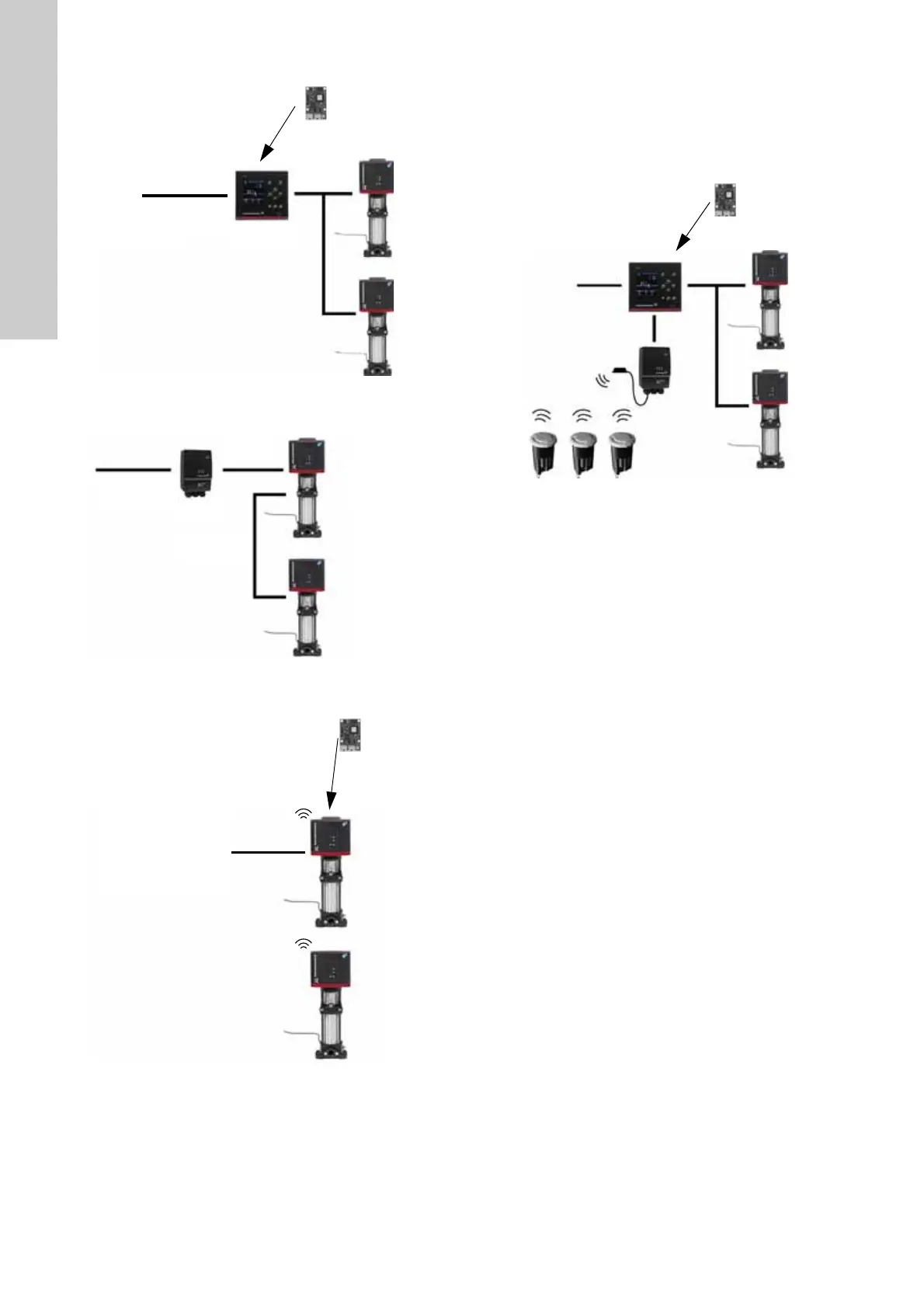
3.4 CIM 500 Modbus TCP
Fig. 9 Example of a CIM 500 solution. The module is
installed inside the CU 352 controller
Fig. 10 Example of a CIU 500 solution for Hydro Multi-E model
G
Fig. 11 Example of a CIM 500 solution for Hydro Multi-E
model H and later. Pumps connected via built-in radio
communication (Grundfos Glowpan)
The example for Multi-E model H and later is identical for TPED
model H and later and MAGNA3-D. In all cases, mount the CIM
module in the master pump placed to the left.
For the purpose of redundancy, you can mount a second CIM
module in pump 2 for TPED and Multi-E (not MAGNA3-D). In that
case, all writings from the Modbus master must be sent to both
CIM modules.
Fig. 12 Example of a CIM 500 solution for Demand Driven
Distribution
TM04 2297 3913TM04 2608 3913TM07 0146 4317
Modbus TCP
Sub-
GENIbus
RS-485
Hydro MPC
(CU 352)
CIM 500
CIU 500
GENIbus
RS-485
Modbus TCP
CRE with
Hydro Multi-E
add-on
Sub-GENIbus
RS-485
TM05 9498 3913
Sub-
GENIbus
RS-485
Modbus TCP
Service
port
CU 354
CIU 260 +
CIM 040
DDD sensors
CIM 500
 Loading...


