14 / 20
Impeller (pos. 49/49a) and neck ring complete (pos. 45a)
If the tolerance (clearance) between the impeller (wear ring, (pos. 49c)) and the neck ring, (pos. 45), is too big, replace
the worn part(s).
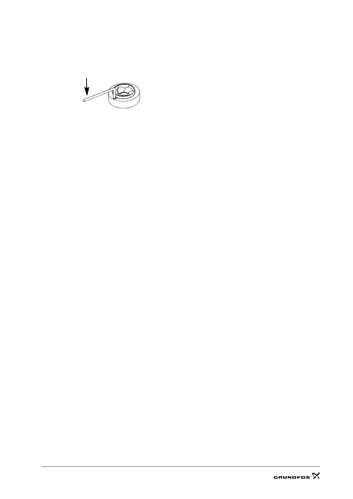
Impeller (wear ring (pos. 49c))
If the wear ring is worn or deformed, remove it by pushing it up and free of the impeller using the holder, (pos. C), and
the puller, (pos. G). See fig. 5.
Fig. 5
Neck ring (pos. 45)
Push the neck ring retainer, (pos. 65), up and free of the cup using a screwdriver, and remove the neck ring.
Neck ring complete (pos. 45a)
If the neck ring complete is defective, push it up and free of the chamber/inlet part using two screwdrivers, and replace it.
Bearing ring with driver (pos. 47a) and stationary bearing ring (pos. 47)
The maximum permissible difference between the diameters of the bearing rings is 0.3 mm. If the difference is greater,
the worn part(s) must be replaced.
Bush (pos. 47c)
The maximum permissible difference between the diameters of the bush and the shaft is 1.0 mm. If the difference is
greater, the worn part(s) must be replaced.
Stationary bearing ring (pos. 47), bush (pos. 47c) and retaining rings (pos. 47d and 47e)
Place the chamber on a level and solid surface with the neck ring complete, (pos. 45a), uppermost.
Support the hub in the chamber. Make sure that the bearing ring, bush and retaining ring can pass freely out of the
chamber when they are pressed/knocked out of the chamber.
Stationary bearing ring (pos. 6g) and rotating bearing ring (pos. 47b)
The maximum permissible difference between the diameters of the stationary and the rotating bottom bearing ring is
0.3 mm. If the difference is greater, the worn part(s) must be replaced.
Stationary bearing ring (pos. 6g)
Slacken the screw, (pos. 31), and remove it together with the washer, (pos. 32).
Place the puller, (pos. D), underneath the bearing ring (pos. 6g).
Screw the hexagon socket head screw, (pos. E), into the puller.
Pull the puller against the bearing ring, and at the same time screw the hexagon socket head screw against the bottom
of the base.
Make sure that the hexagon socket head screw is in the centre of the bottom bearing.
Turn the hexagon socket head screw until the bearing ring is free of the base.
Rotating bearing ring (pos. 47b)
Slacken the hexagon socket head screw, (pos. 67), and remove it together with the washers, (pos. 66b and 66).
Pull the bearing ring off the shaft.
TM00 7233 0996

 Loading...


