15 / 20
4.9 Assembly of chamber stack
Before assembly, clean and check all parts. Parts that are defective or do not comply with the above measurements
due to wear should be replaced by new parts.
Impeller (pos. 49 and 49a)
Press the wear ring, (pos. 49c), carefully down over the impeller skirt.
Make sure to push the ring straight down and home against the impeller skirt and take care not to damage the impeller.
Neck ring (pos. 45)
Place the neck ring, (pos. 45), in the cup.
Fit the neck ring retainer, (pos. 65), with the four driving dogs pointing downwards. Turn the neck ring retainer until it
engages with the neck ring.
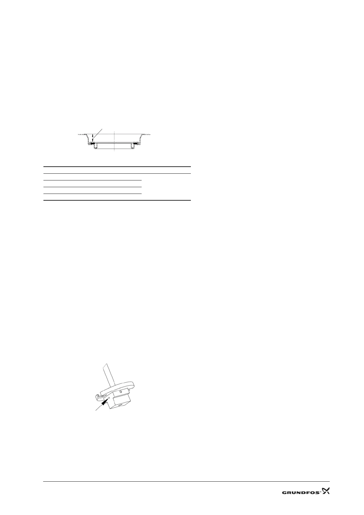
Knock the neck ring retainer against the cup using the punch, (pos. F). See check measurements below.
Fig. 6
It must be possible to move the neck ring freely (sideways) between the neck ring retainer and the cup.
Neck ring complete (pos. 45a)
Fit the neck ring complete and knock/press it home against the chamber/inlet part using the punch, (pos. F).
Stationary bearing ring (pos. 47), bush (pos. 47c) and retaining rings (pos. 47d and 47e)
Place the chamber on a level and solid surface with the neck ring complete, (pos. 45a), face downward.
Support the hub in the chamber. Knock/press the bearing ring/bush and retaining ring home against the chamber using
the punch, (pos. B).
Stationary bearing ring (pos. 6g)
Knock/press the bottom bearing into the base (against the shoulder) using the punch, (pos. B).
Rotating bearing ring (pos. 47b)
Fit the bearing ring (pos. 47b) to the shaft.
Fit the washers, (pos. 66 and 66b). Lubricate the hexagon socket head screw, (pos. 67) and tighten it. See 2. Tightening
torques and lubricants.
Chamber stack (pos. 80)
Place the holder for dismantling and assembly, (pos. A), in a vice and tighten it.
Make sure that the ring fitting the inlet part, (pos. 44), is placed in the holder.
When assembling the chamber stack, use the holder hole marked "Assembly". See fig. 7.
Fig. 7
Place the shaft in the holder.
Turn the shaft so that the hole in the shaft and the holder hole marked "Assembly" are in the same position. Fit the pin
into the hole to hold the shaft.
Fit the inlet part, (pos. 44), with neck ring complete, (pos. 45a), and turn it so that the fixing lugs for straps on the inlet
part are above the cutouts in the holder. Make sure that the inlet part engages with the holder.
TM01 1955 2201
Pump Nominal height X [mm] Tolerance [mm]
CR(N) 32 10.1
±0.2
CR(N) 45 15.5
CR(N) 64 11.5
CR(N) 90 12.1
TM01 2028 0998
X

 Loading...


