16 / 20
Continue the assembly as follows:
Symbols refer to 5. Order of assembly for chambers and impellers.
Fit the impeller and the split cone, (pos. 49b).
Press the impeller home, and knock the split cone into the impeller hub using the key, (pos. I).
Hold the impeller with the hook spanner, (pos. N), and fit and tighten the split cone nut, (pos. 48). See 2. Tightening
torques and lubricants.
Fit the top chamber, (pos. 3), and turn it so that the holes for straps are aligned to the fixing lugs for straps on the inlet
part.
Press the top chamber home against the chamber below or the inlet part.
Fit the impeller and the split cone, (pos. 49b).
Press the impeller home, and knock the split cone into the impeller hub using the key, (pos. I).
Hold the impeller with the hook spanner, (pos. N), and fit and tighten the split cone nut, (pos. 48). See 2. Tightening
torques and lubricants.
Fit the chamber, (pos. 4), and press it home against the chamber below or the inlet part.
Fit the impeller and the split cone, (pos. 49b).
Press the impeller home, and knock the split cone into the impeller hub using the key, (pos. I).
Hold the impeller with the hook spanner, (pos. N), and fit and tighten the split cone nut, (pos. 48). See 2. Tightening
torques and lubricants.
Slide the bearing ring with driver, (pos. 47a), over the split cone nut. It must engage with the split cone nut.
Fit the chamber with bearing, (pos. 4a), and press it home against the chamber below.
Fit the straps, (pos. 26a), the washers, (pos. 26c), and the screws, (pos. 26b). Lubricate the screws and tighten.
See 2. Tightening torques and lubricants.
Remove the pin holding the shaft, and lift the chamber stack off the holder.
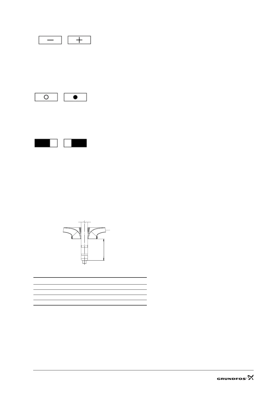
Check the impeller position. See fig. 8.
Further assembly. See 4.7.2 Assembly.
Fig. 8
TM01 2467 2201
Pump Nominal height Y [mm]
CR(N) 32 70
CR(N) 45 71
CR(N) 64 70
CR(N) 90 78
Y
49

 Loading...


