10 / 20
4.5 Replacement of shaft seal
4.5.1 Dismantling
To enable replacement of shaft seal, motors up to and including 7.5 kW/10.0 HP must be removed; motors larger than
7.5 kW need not be removed.
Slacken the screws, (pos. 7a), and remove them together with the coupling guards, (pos. 7).
Slacken the screws, (pos. 9), and remove them together with the coupling, (pos. 8).
Pumps with motors up to and including 7,5 kW/10 HP
Slacken and remove the screws, (pos. 28a), and the nuts, (pos. 36a).
Carefully lift the motor free of the pump using lifting equipment suitable for the motor size.
Slacken the screws, (pos. 58a), and remove them together with the seal carrier, (pos. 58).
Clean the shaft end. Slacken the three screws, (pos. 113), so that they do not touch the shaft.
The screws should be slackened only so much that the shaft seal can be removed from the shaft.
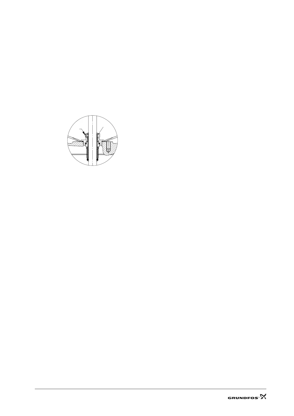
Loosen the shaft seal, (pos. 105), from the pump head using two screwdrivers. See fig. 3, and pull it off the shaft.
Fig. 3
4.5.2 Assembly
Clean and smooth the shaft before fitting the shaft seal. Use the holder with emery cloth supplied with the shaft seal kit.
Apply O-ring grease to the shaft end and the O-ring of the shaft seal, (pos. 105). Press the shaft seal down on the shaft
and against the pump head.
Remove excess grease from the shaft end using a cloth.
Fit the seal carrier, (pos. 58).
Lubricate the screws, (pos. 58a). Fit the screws and tighten diagonally. See 2. Tightening torques and lubricants.
Press the pump shaft home and fasten the shaft seal on the shaft with the screws, (pos. 113). See fig. 1.
Lift the pump shaft and insert the forked distance piece, (pos. H), between the shaft seal, (pos. 105), and the seal carrier,
(pos. 58). See fig. 1.
Pumps with motors up to and including 7,5 kW/10 HP
Fit the motor and turn it to the required terminal box position.
Lubricate the screws, (pos. 28a), and the nuts, (pos. 36a). Fit them and tighten diagonally to the torque stated.
See 2. Tightening torques and lubricants.
Fit the coupling, (pos. 8), on the shaft so that the top of the pump shaft is flush with the bottom of the clearance chamber
in the coupling. See fig. 2.
Lubricate the hexagon socket head screws, (pos. 9). Fit the screws, tighten and leave loose.
Check that the gaps either side of the coupling halves are equal.
Tighten the hexagon socket head screws, (pos. 9), two and two (one side at a time). See 2. Tightening torques and
lubricants.
Pull the forked distance piece, (pos. H), free of the shaft, turn it and store it on the screw, (pos. 58a).
Fit the coupling guards, (pos. 7), and fasten them with the screws, (pos. 7a).
TM01 2027 0998
105
113
 Loading...


