8 / 20
4.2 Replacement of motor
4.2.1 Dismantling
Slacken the screws, (pos. 7a), and remove them together with the coupling guards, (pos. 7).
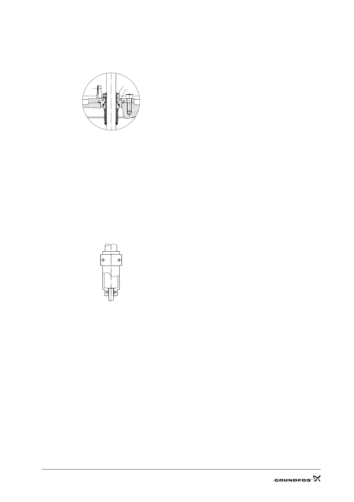
Keep the shaft seal in position on the shaft by inserting the distance piece, (pos. H), between the shaft seal, (pos. 105),
and the seal carrier, (pos. 58). See fig. 1.
Fig. 1
Slacken the screws, (pos. 9), and remove them together with the coupling, (pos. 8).
Slacken and remove the screws, (pos. 28a), and the nuts, (pos. 36a).
Carefully lift the motor free of the pump using lifting equipment suitable for the motor size.
4.2.2 Assembly
Before assembly, clean all parts.
Fit the motor and turn it to the required terminal box position.
Lubricate the screws, (pos. 28a), and the nuts, (pos. 36a), with THREAD-EZE. Fit them and tighten diagonally.
See 2. Tightening torques and lubricants.
Before fitting the coupling, check that the forked distance piece, (pos. H), is still inserted between the shaft seal,
(pos. 105), and the seal carrier, (pos. 58).
Fit the coupling, (pos. 8), on the shaft so that the top of the pump shaft is flush with the bottom of the clearance chamber
in the coupling. See fig. 2.
Fig. 2
Lubricate the hexagon socket head screws, (pos. 9). Fit the screws, tighten and leave loose.
Check that the gaps either side of the coupling halves are equal.
Tighten the hexagon socket head screws, (pos. 9), two and two (one side at a time). See 2. Tightening torques and
lubricants.
Pull the forked distance piece, (pos. H), free of the shaft, turn it and store it on the screw, (pos. 58a).
Fit the coupling guards, (pos. 7), and fasten them with the screws, (pos. 7a).
TM01 1927 0698TM01 1930 0698
105
58
H
 Loading...


