Dismantling Procedures CR, CRN 32•45•64•90
When Should A Part Be Replaced?
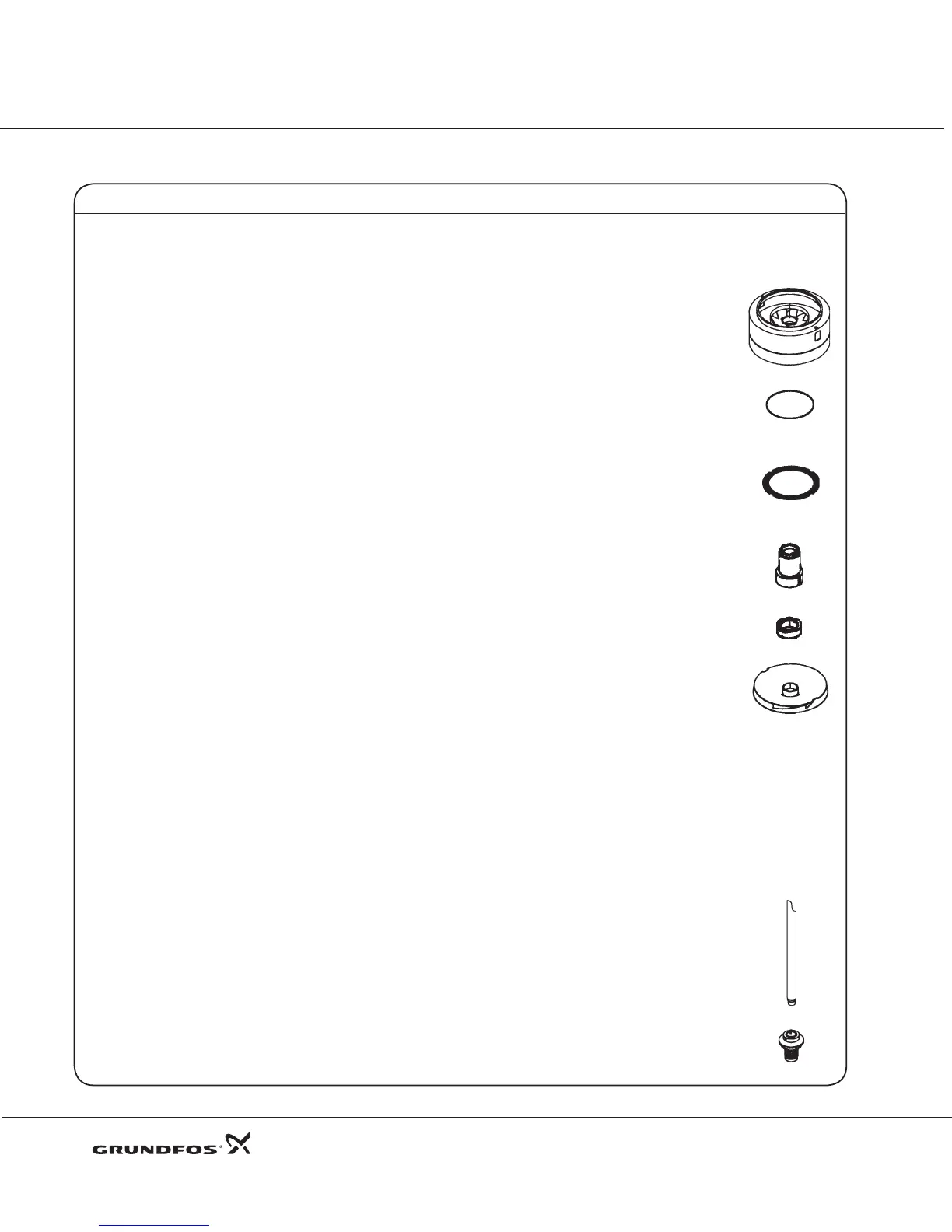
Part Position(s) Minimum Operating Condition
Pump Head 2 Excessive pitting of these castings could cause leaks. Rusted
castings should have all seating areas cleaned to ensure proper
seating of O-rings.
Suction/Discharge 6
Base
Chambers 3, 4a, 4 Same as for impellers.
O-rings 37, 38, 38a, 100 Should be soft and pliable with no visible scars. Since they
are easily damaged and fairly inexpensive, it is recommended
they be replaced whenever the pump is disassembled.
Neck Ring 45 Should be free of visible wear on the inside edges.
Inside diameter for:
CR, CRN 32 = 66.2 mm
CR, CRN 45 = 73.9 mm
CR, CRN 64 = 86.3 mm
CR, CRN 90 = 93.8 mm
Bearing Ring 47a The diameter size difference between the Bearing Ring (Pos. 47a)
and the Bearing (47-47c) xed inside the intermediate
chambers should be no greater than 0.4 mm.
Bushing and Bearings 6g, 47, 47b, 47c The diameter size difference between the Bearing Ring
(Pos. 47a) and the Bearing (Pos. 47-47c) xed inside the intermediate
chambers should be no greater than 0.4 mm.
Impellers 49 (a, d, e & i) Should be free from physical markings except for the guide
vane welds. Any additional identations may result from:
(1) Cavitation - the implosion of vapor "bubbles" within the
impeller stack. Make sure the Net Positive Suction Head
Available for the pump meets the minimum Net Positive
Suction Head Required for the pump when runnning at the
required ow.
(2) Improper coupling height - If the coupling is not set to the
proper height (see step 54 & 57 of the Reassembly procedures) the
impellers are not suspended as they should be, but instead
they rub against the chambers, either above or below, causing
contact wear.
(3) Worn groove to Impeller Wear Ring (Pos. 49c) from system
sediments. Wear rings should be replaced, or impeller complete if
threaded area for split cone nut is damaged.
Shaft 51 Should show no signs of gouging or wear throughout its total
length. Use emery tool to remove shaft seal set screw marks.
Stack Compression Spacer 60 Should always be replaced.
Shaft Seal
Cartridge Complete 105 (a, b & c) Should seal without leakage
Refer to the Parts List and Kits section for a list of material numbers and spare part kits.
12
 Loading...


