The motor, motor stool, and/or bearing ange
will be assembled as a complete unit. Place
the entire assembly onto the pump head.
Lubricate the threads on the 8 mm hex socket
Retaining Screws (Pos. 28) with Gardolube or
Thread-Eze. Install and diagonally torque to
46ft.-lbs./62Nm. If the motor was removed
during disassembly, reattach the motor.
Lubricate the threads of the Motor Bolts (Pos.
28a) and then tighten the bolts diagonally to:
30 ft.- lbs./41 Nm for 1/2" x 13 UNC, 3-40 HP
59 ft.- lbs./80 Nm for 5/8" x 11 UNC, 50-60 HP
To install the Coupling Halves
(Pos. 10a), position the coupling
half relief area flushed with the
top of the shaft as shown in the
diagram. Lubricate the threads on
the 8 mm hex socket Coupling Screws
(Pos. 9) with Gardolube or Thread-Eze.
Loosely thread the screws in place.
Reassembly Procedures CR, CRN 32•45•64•90
Push the shaft downward (for Back-to-
Back units, continue downward pressure
as the inboard seal spring tension may lift
the shaft). Evenly tighten, then torque the
three 3 mm set screws to 6 ft.-lbs./8Nm.
Place a second adjusting fork
on top of the seal collar. Install
the Coupling Halves (Pos. 10a).
Lubricate the threads on the
8 mm hex socket Coupling Screws
(Pos. 9) with Gardolube or Thread-Eze.
Loosely thread the screws in place.
Torque the 8 mm hex socket coupling
screws to 63 ft.-lbs./85Nm. This step
is the same for all pump types (in the
photo a tandem seal version is shown).
61
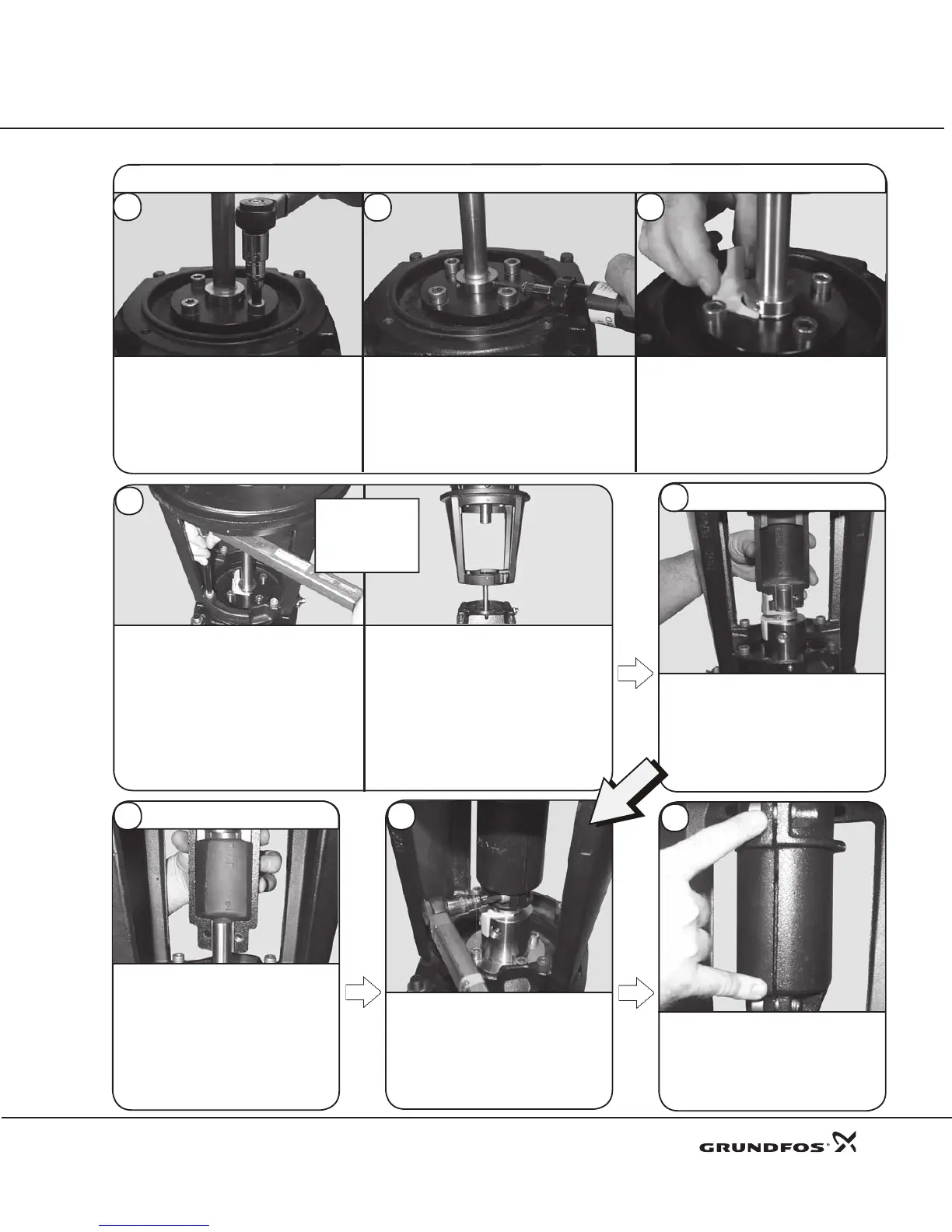
Li ft th e sh aft and i nsert t he
adjusting fork under the seal collar.
Lo we r a nd s eat t h e Ret a in er
(Pos. 58). Lubricate the threads of
the 8 mm hex socket Retaining
Screws (Pos. 58a) with Gardolube
or Thread-Eze. Install and diagonally
torque the screws to 46ft.-lbs./62Nm.
62
Make sure the gaps on both sides of
the coupling are even. Applies to all
pump types.
Attach the motor and motor stool separately
to the pump head. Lubricate the threads
on the 8 mm hex socket Retaining Screws
(Pos. 28) with Gardolube or Thread-
Eze. Install and diagonally torque to
46ft.-lbs./62Nm. Place the motor
ont o the mo tor st ool , lub ric ate
the threa ds of the M otor B o lts
(Pos. 28a) and tighten the bolts diagonally to
30 ft.-lbs./41Nm.
58
Placement of the
Motor Stool (Pos. 1a)
differs depending on
model size.
15 HP
and up
3 - 10 HP
and Up
Tandem Seal Only
59
Standard, Cool Top®, &
Back-to-Back Seal Units
60
21
Standard, Cool Top®, & Back-to-Back Seal Units
56
57
55
ALL PUMP TYPES
 Loading...


