Refer to the diagrams on pages
22-26 for the appropriate staging
sequence for your particular
model pump. Once the last
chamber has been installed,
continue with step 9.
Hook the Chamber Straps (Pos. 26a)
through the Base Interface (Pos. 44).
Position top end of straps into relieved
area of the Top Chamber (Pos. 3).
Place the Washer (Pos. 26c) and Allen
Screws (Pos. 26b) loosely threaded
into the straps. Allen screws must
be pre-lubricated with Gardolube.
Torque evenly to 11 ft.-lbs./15 Nm.
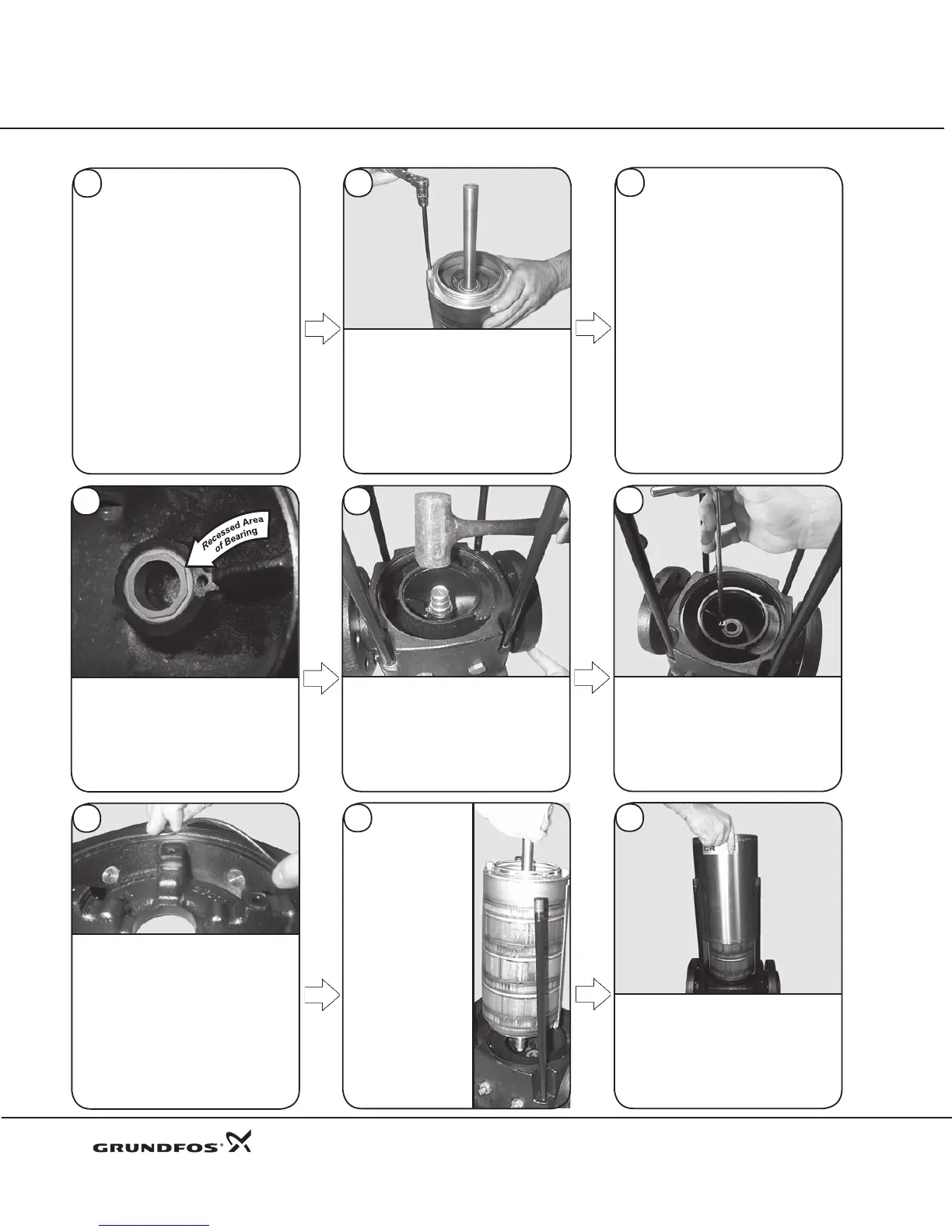
Remove the holding pin from the
assembly/dismantling fixture.
Lift the STACK® (Pos. 80) out of
the xture. Lay the stack on a at
surface and check the rotation and
end play*. Movement should be
free and without binding.
* End play is shaft travel (up and down)
through the chambers.
10
8
9
14
Reassembly Procedures CR, CRN 32•45•64•90
Place the Washer (Pos. 32) and
the 5 mm Allen Screw (Pos. 31)
into the suction/discharge base.
Torque the screw to 6ft.-lbs/8Nm.
To install the Bottom Bearing (Pos.
6g) into the Suction/Discharge Base
(Pos. 6), place the bearing into the
hole provided in the base. Ensure
the recessed area of the bearing
is located where the hole for the
allen screw is machined in the base.
Use the bearing punch (00SV0015
or 00SV0212) and a rubber mallet
to drive the bearing into place.
13
11
12
16
15
Place the STACK®
into the suction/
discharge base. Rotate
the straps so they center
between the Staybolts
(Pos. 26) or line up
with the suction and
discharge ports of the
base. Recheck the shaft
end play (shaft travel up
and down) and the shaft
rotation. Movement
should be free without
binding. If binding
occurs stop, remove
the stack and check
clearance between the
bottom shaft bearing,
be a ri n g cl a mpi ng
washer and the bearing
in the base.
Place Sleeve (Pos. 55) into the
suction/discharge base. Press
sleeve firmly into the base.
Place the Sleeve O-ring of EPDM or
FKM (Pos. 37) into the recessed groove
in the Pump Head (Pos. 2, 2b, & 2c)
and the suction/discharge base for
standard units. Specialty O-rings in
FXM or FFKM (Pos. 37a) are used in
the lower hot section of the pump in
Cool Top equipped pumps. Lubricate
the O-rings with Rocol (00RM2924)
or Dow Corning 111. Never use oil or
grease as this will attack the O-rings.
14
 Loading...


