English (GB)
11
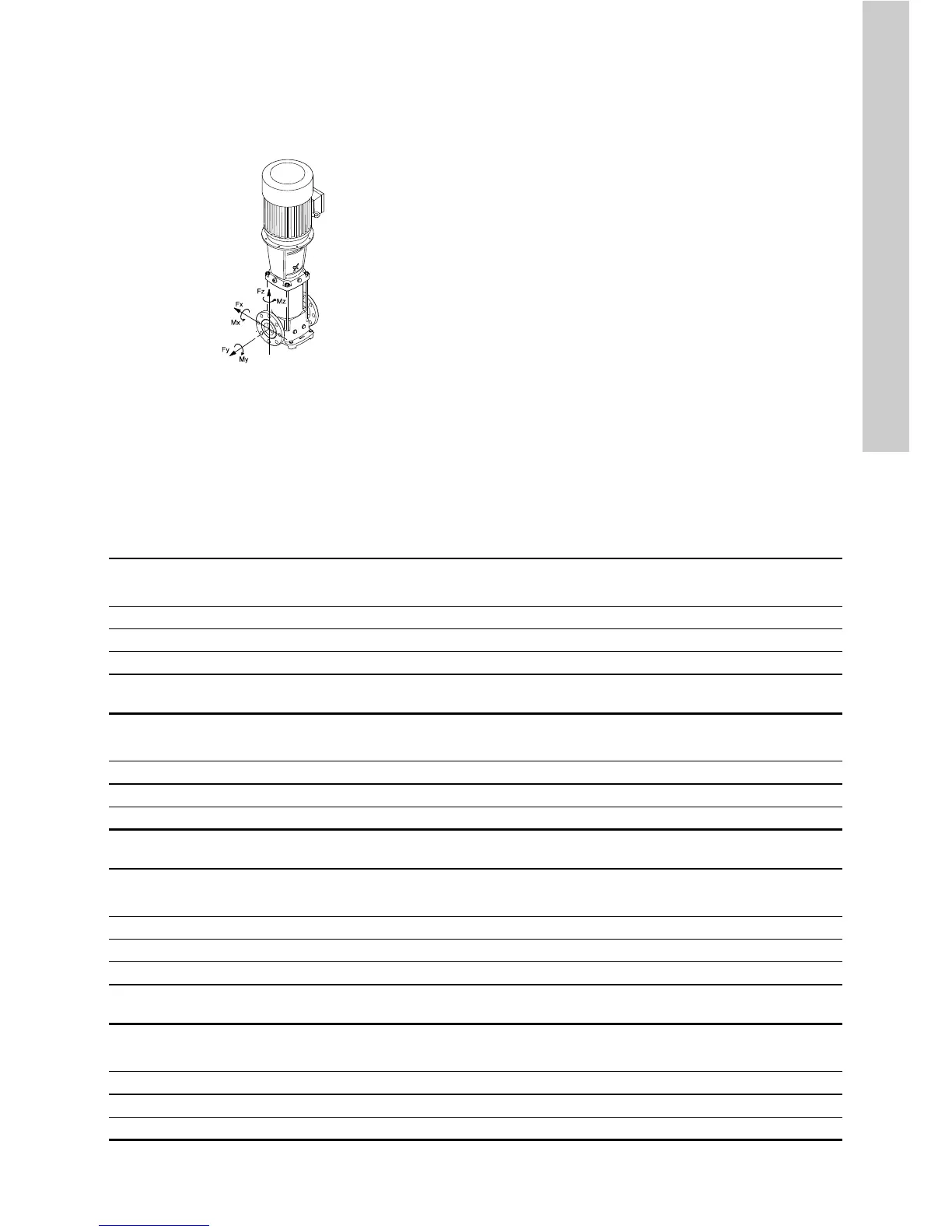
3.1.7 Flange forces and torques
If not all loads reach the maximum permissible value
stated in the tables below, one of these values may
exceed the normal limit. Contact Grundfos for further
information.
Fig. 23 Flange forces and torques
The following tables represent the values that apply
according to the material quality.
Force limits for CR pumps
Force limits for CRN pumps
Torque limits for CR pumps
Torque limits for CRN pumps
TM04 0346 2013
Y-direction: Inlet or outlet
Z-direction: Direction of chamber stack
X-direction: 90 ° from inlet or outlet
Flange, DN
[mm]
CR
Force, Y-direction
[N]
Force, Z-direction
[N]
Force, X-direction
[N]
100 95 1256 1013 1125
150 125 and 155 1875 1519 1688
200 185, 215 and 255 2513 2025 2250
Flange, DN
[mm]
CRN
Force, Y-direction
[N]
Force, Z-direction
[N]
Force, X-direction
[N]
100 95 2513 2025 2250
150 125 and 155 3750 3038 3375
200 185, 215 and 255 5025 4050 4500
Flange, DN
[mm]
CR
Torque, Y-direction
[Nm]
Torque, Z-direction
[Nm]
Torque, X-direction
[Nm]
100 95 375 475 625
150 125 and 155 625 775 1000
200 185, 215 and 255 900 1075 1375
Flange, DN
[mm]
CRN
Torque, Y-direction
[Nm]
Torque, Z-direction
[Nm]
Torque, X-direction
[Nm]
100 95 750 950 1250
150 125 and 155 1250 1550 2000
200 185, 215 and 255 1800 2150 2750

 Loading...


