Selection and sizing
CR, CRI, CRN, CRE, CRIE, CRNE
24
Minimum inlet pressure - NPSHA
Calculation of the inlet pressure "H" is recommended in
these situations:
• The liquid temperature is high,
• The flow is significantly higher than the rated flow,
• Water is drawn from depths,
• Water is drawn through long pipes,
• Inlet conditions are poor.
To avoid cavitation, make sure that there is a minimum
pressure on the suction side of the pump. The
maximum suction lift "H" in feet can be calculated as
follows:
H = p
b
– NPSHR – H
f
– H
v
– H
s
P
b
= Barometric pressure in feet absolute.
(Barometric pressure can be set to 33.9 feet.
At sea level. In closed systems, pb indicates
system pressure in feet.)
NPSHR = Net Positive Suction Head Required in feet.
(To be read from the NPSHR curve at the
highest flow the pump will be delivering).
H
f
= Friction loss in suction pipe in feet.
(At the highest flow the pump will be
delivering.)
H
v
= Vapor pressure in feet. (To be read from the
vapor pressure scale. "H
v
" depends on the
liquid temperature "T
m
").
H
s
= Safety margin = minimum 2.0 feet.
If the "H" calculated is positive, the pump can operate
at a suction lift of maximum "H" feet.
If the "H" calculated is negative, an inlet pressure of
minimum "H" feet is required.
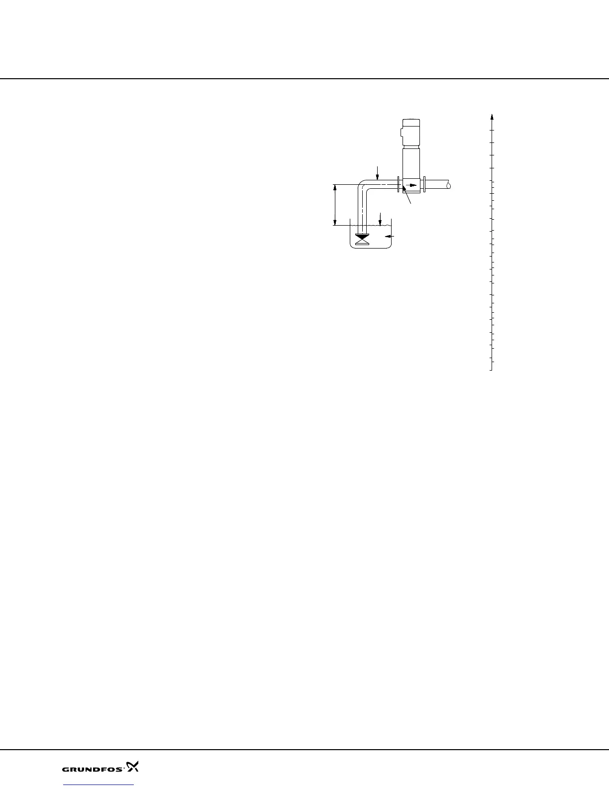
Fig. 26 Minimum inlet pressure - NPSHR
Note: In order to avoid cavitation never, select a pump
whose duty point lies too far to the right on the NPSHR
curve.
Always check the NPSHR value of the pump at the
highest possible flow.
In case a lower NPSHR value is required, see Lists of
variants - on request on page 83.
TM02 7729 3903
66
49
39
33
26
20
16
13
10
6.6
3.3
2.6
2.0
1.3
0.9
0.7
0.3
4.9
250
230
194
212
176
158
140
122
104
86
68
50
32
Hv
(Ft)
tm
(°F)
300
270
280
82
115
148
131
98
320
340
360
370
203
259
328
413
 Loading...


