English (GB)
8
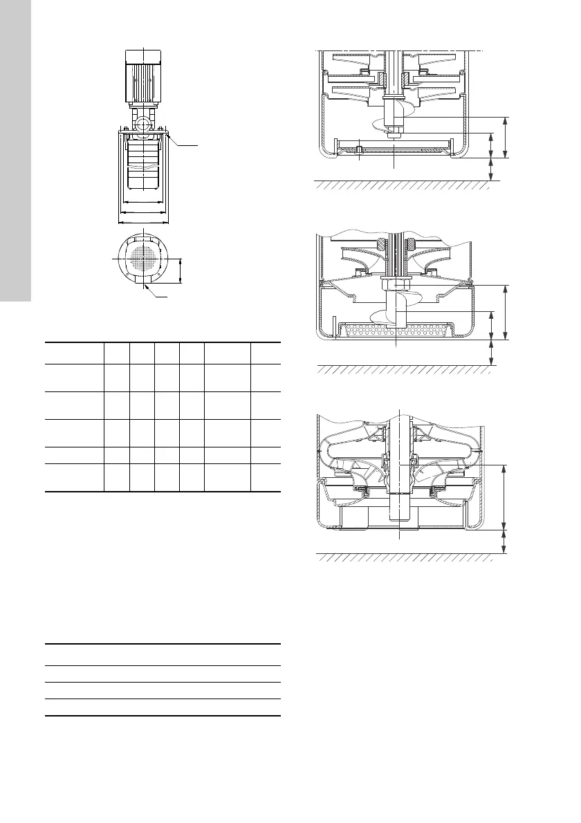
Fig. 8 Vertical installation
Mounting flange dimensions:
6.2 Suction conditions
The bottom of the pump strainer must be at least 25
mm above the bottom of the tank.
The pumps are designed to provide full performance
down to a level of A mm above the bottom of the
strainer.
At a liquid level between A and B mm above the
bottom of the strainer, the built-in priming screw will
protect the pump against dry running.
Note: MTR 32, 45 and 64 pumps have no priming
screw.
Fig. 9 CRK 2, 4 and MTR 1s, 1, 3, 5
Fig. 10 MTR 10, 15, 20
Fig. 11 MTR 32, 45, 64
TM02 8042 4503
Pump type D1 D2 D3 L C X
CRK 2, 4 140 160 180 100
Rp 1 1/4
G 1 1/4
∅7.5
MTR 1s, 1,
3, 5
140 160 180 100
Rp 1 1/4
G 1 1/4
∅9.5
MTR 10,
15, 20
200 225 250 125
Rp 2
G 2
∅9
MTR 32 190 220 250 150 DN 65 ∅12
MTR 45,
64
240 265 290 165 DN 80 ∅12
Pump type A [mm] B [mm]
CRK 2, 4 and MTR 1s, 1, 3, 5 41 28
MTR 10, 15, 20 50 25
MTR 32, 45, 64 70 -
TM05 7223 0813TM05 7224 0813TM05 7225 0813
 Loading...


