English (GB)
13
4.1.4 Assembling the chamber stack
For chamber types, see section 7.4 Order of assembly for
chambers and impellers.
1. Install the inlet part (44) over the pump shaft (51) which is
placed in service tool H1 or H2.
2. Fit the impeller (49 or 49a) which was removed as the last one
during dismantling.
3. Fit a split-cone (49b) in the impeller (49 or 49a).
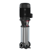
4. Turn service tool C around and knock it against the split-cone
(49b) to fixate the impeller (49 or 49a) to the pump shaft (51).
See fig. 27.
Fig. 27 Fixating the impeller (49 or 49a) to the pump shaft (51)
with service tool C
5. Fit a split-cone nut (48) to the impeller.
6. Hold the impeller (49 or 49a) with a hook spanner. Tighten the
split-cone nut (48) using the service tools C, O and P. See
section 7.1 Torques.
7. Lubricate and fit the bearing (47a). See section
7.2 Lubricants.
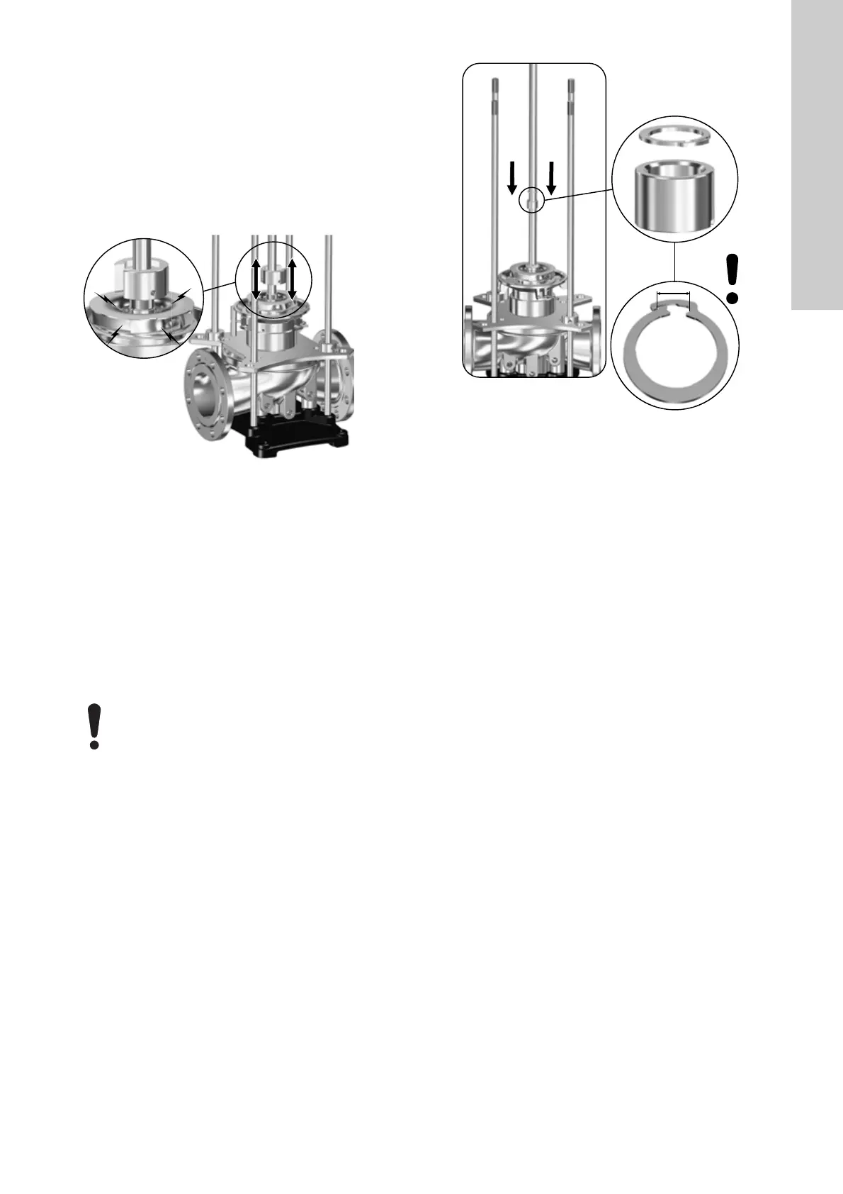
8. For pumps with ∅28 or ∅38 pump shaft: Note that for
pumps with ∅28 or ∅38 pump shaft, you must also fit the lock
ring (47g). See fig. 28.
Make sure that the lock ring (47g) tightens firmly around the
pump shaft and holds the bearing (47a) fixed on the pump
shaft.
Fig. 28 Maximum permissible opening of lock ring (47g)
9. Fit the bottom chamber with bearing (4a), and press it home
on the inlet part (44).
10. Continue installing the remaining chambers (4), split-cone
nuts (48), split cones (49b), impellers (49 or 49a) and
bearings (47a).
11. Fit the outlet part (3b) on the top chamber.
12. Fit the strap (26a), washers (26c) and screws (26b). Lubricate
and tighten the screws. See sections 7.1 Torques and
7.2 Lubricants.
13. Carefully lift the chamber stack with approved lifting
equipment.
14. Follow the assembly instructions described in section
3.2.3 Assembly.
TM07 1896 2218
Do not open the lock ring (47g) further than the
restriction of the integrated locking mechanism. See
fig. 28.
TM07 2073 2618
 Loading...