English (GB)
7
11. Lubricate the threads of the staybolts (26) and cross-tighten
the nuts (36) to the specified torque. See sections 7.1 Torques
and 7.2 Lubricants.
12. Remove service tool J.
13. Clean and smooth the shaft (51) using service tool E with an
emery cloth supplied with the shaft seal kit.
14. Lubricate the o-rings in the shafts seal (51). See section
7.2 Lubricants.
Note: Avoid lubrication on the seal faces.
15. Install the shaft seal (105) on the shaft (51) and press it home
against the pump head cover (2).
16. Tighten the shaft seal hexagon nut to the specified torque by
using service tool A, together with service tools O and P. See
section 7.1 Torques.
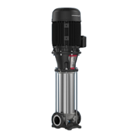
17. Check that the height X is 71 mm ± 2. See fig. 7.
Note: If the measured height is not within the specifications,
the pump has not been assembled correctly and the pump
must be dismantled to find the reason.
Fig. 7 Height measurement X
18. Install the cylindrical pin (10) in the pump shaft (51).
19. Install the coupling halves (10a).
20. Lubricate and tighten the screws (9), but leave loose. See
section 7.2 Lubricants.
21. Check that the gaps on either side of the coupling halves are
equal. See fig. 8.
Fig. 8 Gap between coupling halves
22. Tighten the three set screws (113) to the specified torque. See
section 7.1 Torques.
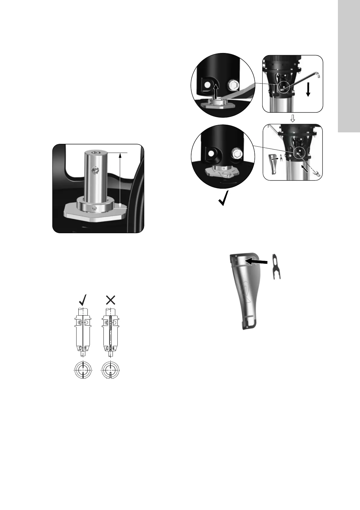
23. Lift the pump shaft with a crowbar and insert the adjusting fork
F. See fig. 9.
Fig. 9 Lifting pump shaft and fitting adjusting fork.
24. Cross-tighten the screws (9) to the specified torque. See
7.1 Torques.
25. Pull the adjusting fork F free of the shaft (51) and place it on
the backside of one of the coupling guards (7). See fig. 10.
Fig. 10 Fitting adjusting fork F on the backside of coupling
guard (7)
26. Install the coupling guards (7) and tighten the screws (7a).
See section 7.1 Torques.
TM07 0969 1018TM07 1744 2218
TM07 0868 1418TM07 1743 2218
 Loading...