2
CONTENTS
Page
1. Symbols used in this document 2
2. General 2
3. Technical data 2
4. Connecting the DDI to the PROFIBUS-DP V0 2
4.1 PROFIBUS-DP V0 2
4.2 Device master data file (GSD) 2
5. Electrical connections 2
5.1 PROFIBUS cabling and start-up, possible faults 2
5.2 Connection to the DDI pump 3
5.3 Accessories: connector for PROFIBUS-DP 3
5.4 Installation diagram with terminal resistor 3
6. Operating the pump using PROFIBUS-DP 4
6.1 Activating the PROFIBUS 4
6.2 Communication between the PROFIBUS master and
the pump 5
6.3 Data protocol 5
6.4 Data transmission (programming examples) 8
7. Disposal 8
1. Symbols used in this document
2. General
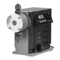
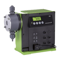
These installation and operating instructions contain all the
information required for connecting a DDI dosing pump with
PROFIBUS option to the PROFIBUS-DP V0 as a slave.
If you require further information or if any problems arise, which
are not described in detail in this manual, please contact the
nearest Grundfos Alldos company.
3. Technical data
PROFIBUS
PROFIBUS-DP V0.
Auto-detect baud rate
The following baud rates are recognised automatically:
12 Mbps, 6 Mbps, 3 Mbps, 1.5 Mbps, 500 kbps, 187 kbps,
93.75 kbps, 45.45 kbps, 19.2 kbps, 9.6 kbps.
Maximum permissible baud rate (transmission speed)
1.5 Mbps.
Bus connection
Via Y-M12 connector.
Identification of DDI pumps with PROFIBUS-DP option
The following is indicated on the DDI pump nameplate:
Enclosure class
IP 65.
4. Connecting the DDI to the PROFIBUS-DP V0
4.1 PROFIBUS-DP V0
DP (Decentralised Peripherals) is the communication protocol for
fast data transfer at field level. Using this protocol, the bus master
(e.g. SPS) communicates with decentralised field devices/bus
slaves (e.g. dosing pumps, analysis devices) via a fast serial port.
The communication functions are determined by the DP-V0
performance level. DP V0 stands for simple, fast, cyclic and
deterministic exchange of process data between the bus master
and the assigned slave devices.
4.2 Device master data file (GSD)
The DDI pump with PROFIBUS-DP option is integrated into the
PROFIBUS-DP V0 network using the device master data file
(GSD), which must be integrated into the engineering system of
the PROFIBUS network. This file contains the properties of the
device, specifications on its communication capabilities and
additional information such as diagnosis values.
A CD for integration of the DDI pump with PROFIBUS-DP option
into the device communication of the dosing pump (slave)/master
(SPS) is supplied with the PROFIBUS-DP.
The CD contains
• a GSD file (device master data file)
• an illustration of the DDI pump for integration into visualisation
programs
• documentation.
5. Electrical connections
5.1 PROFIBUS cabling and start-up, possible faults
5.1.1 Signal line
• Short-circuit between line A, line B or screen.
• Line A and line B interchanged or crossed.
• Line A, line B or screen interrupted.
5.1.2 Bus termination
• One end of the bus segment is not terminated.
• Two or more bus terminal resistors are switched on.
• The bus terminal resistor is not powered.
• No bus terminal resistor after a repeater without slaves.
Warning
These installation and operating instructions are
also available on www.Grundfosalldos.com.
Prior to installation, read these installation and
operating instructions. Installation and operation
must comply with local regulations and accepted
codes of good practice.
Warning
If these safety instructions are not observed,
it may result in personal injury!
Caution
If these safety instructions are not observed,
it may result in malfunction or damage to the
equipment!
Note
Notes or instructions that make the job easier
and ensure safe operation.
Warning
First read the installation and operating
instructions for the DDI pump. Only the
additional functions are described in this manual.
Control variant Description
AP With PROFIBUS
APF With PROFIBUS and Flow Monitor
Warning
IP 65 can only be ensured if the connectors have
been screwed on correctly.
Warning
Electrical connections must only be carried out
by qualified personnel!
First read the installation and operating
instructions for the DDI pump.
IP 65 can only be ensured if the connectors have
been screwed on correctly.
 Loading...
