3
5.1.3 PROFIBUS cable
• The bus cable installed is too long or the transmission speed
is too high.
• Incorrect cable type installed (not a PROFIBUS cable).
• Cables from different manufacturers installed.
• The branch lines are too long.
• The minimum cable length of 1 metre between the devices on
the bus has not been observed.
5.1.4 Electrical environment
• No or insufficient equipotential bonding conductors.
• Insufficient signal level on the RS-485 line.
• Electromagnetic interference problems:
– capacitive coupling
– discharges
– leakage currents on screened cables
– potential sources of interference, such as frequency
converters, contactors, motors, etc.
– PROFIBUS cable installed too close to potential sources of
interference.
• Incorrect power supply concept.
• Unsuitable earthing concept.
• Screened cable not earthed on both sides. Earthing does not
cover a sufficiently large area.
5.1.5 Bus settings
• No master in the system.
• Bus option not set to "on".
• Incorrect bus address set.
• Bus address assigned more than once.
• Incorrect baud rate set for the master.
• Too many devices (more than 32) in a single bus segment.
5.2 Connection to the DDI pump
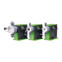
Fig. 1 Connection to DDI 209
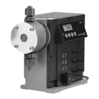
Fig. 2 Connection to DDI 222
• For the PROFIBUS-DP, attach a Y-M12 connector to socket 6
of the pump.
• Connect the bus to the sockets of the Y-M12 connector using
2-pin PROFIBUS cables.
5.2.1 Pin assignment, socket 6
5.2.2 Bus connection
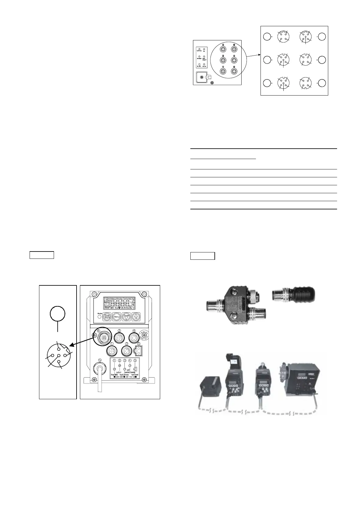
If the pump is the last device on the bus, it must be equipped with
a bus terminal resistor.
• Screw the bus terminal resistor onto the Y-M12 plug.
5.3 Accessories: connector for PROFIBUS-DP
Fig. 3 Connector for PROFIBUS-DP
5.4 Installation diagram with terminal resistor
Fig. 4 Installation diagram
Note
For additional information, please refer to the
PROFIBUS Guidelines (PROFIBUS-DP/FMS
Installation Guidelines, Order No. 2.111) from the
Profibus User Organisation (www.profibus.com).
TM03 6582 4506
6
1
2
3
4
5
TM03 6583 4506
Socket 6
Used for
Pin Assignment
1 + 5 V Bus terminal resistors
2 RxD/TxD-N Received/sent data (line A)
3GND
4 RxD/TxD-P Received/sent data (line B)
5 Screen/protective earth
Note
To ensure the fault tolerance of the PROFIBUS
system in the event of a device fault or when a
device is replaced, a separate active bus terminal
resistor is recommended.
TM03 6584 4506TM03 6585 4506
1
3
5
42
1
2
3
4
5
6
1
2
3
4
optional
5
1
2
3
4
2
1
4
3
1
2
3
4
5
1
2
4
3

 Loading...