English (GB)
16
5. Alignment
5.1 Preliminary alignment
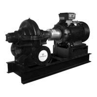
The pump and motor are pre-aligned on the base frame from the
factory. Some deformation of the base frame may occur during
transport and it is therefore essential to check alignment at the
installation site before final grouting.
Inaccurate alignment results in vibration and excessive wear on
the bearings, shaft and wear rings.
Carry out alignment of the motor by placing shims of different
thickness under the motor. If possible, replace several thin shims
with one thick shim.
The preliminary alignment procedure has four steps:
1. Checking coupling clearance
Make sure that the gap between the coupling halves is equal to
the values in the table and that the keyways are 180 ° displaced.
2. Checking soft foot on pump and motor
A pump or a motor having a soft foot can be compared to sitting
down at a table and finding that the table rocks when someone
leans on it. Technically, it is a condition where the feet of a motor
or a pump are not at the same level as the base plate.
To check for soft foot, set the pump or motor on its base plate and
bolt it down. Set a dial gauge on one foot, loosen the hold-down
bolt, and watch the dial gauge. If the dial gauge indicator moves
while loosening the bolt, the pump or motor has soft foot. The
movement measured by the dial gauge indicates how many
shims you need to level the pump or motor. Repeat this
procedure at all four corners.
If the pump was installed a long time ago, the stresses induced in
the pump housing by soft foot can cause permanent deformation
of the housing.
3. Checking parallel alignment
Place a straight edge across both coupling rims at the top, the
bottom and both sides. See fig. 8. After each adjustment, recheck
all features of alignment. Parallel alignment is correct when the
measurements show that all points of the coupling faces are
within 0.2 mm of each other.
Fig. 8 Checking parallel alignment
4. Checking angular alignment
Insert a pair of inside callipers or a taper gauge at four points at
90 ° intervals around the coupling. See fig. 9. The angular
alignment is correct when the measurements show that all points
of the coupling faces are within 0.2 mm of each other.
Fig. 9 Checking angular alignment
Recheck the coupling clearance and tighten the set screws on the
couplings.
Tightening torques
5.2 Final alignment
1. Let the pump run until it has reached its operating
temperature under normal operating conditions,
approximately 1 hour.
2. Stop the pump.
3. Remove the coupling guard.
4. Check the alignment on the coupling by means of dial gauges.
See below.
Checking coupling alignment by means of dial gauges
Alternatively, use laser equipment for the final alignment.
Fig. 10 Dial gauge arrangements;
the end view of the coupling seen from the motor
DANGER
Electric shock
Death or serious personal injury
- Before starting work on the pump, make sure that
the power supply has been switched off and that it
cannot be accidentally switched on.
Carry out alignment of the motor only, as pipe strain
will occur if the pump is shifted.
For a coupling with an
outside diameter of ∅ [mm]
Coupling clearance [mm]
Nominal Tolerance
∅90-213 3.2 0/-1
∅251-270 4.8 0/-1
∅306-757 6.4 0/-1
TM03 0209 4504
TM03 0213 4504
Description Dimensions
Tightening torque
[Nm]
Hexagon head
screw
M6 10
M8 12
M10 23
M12 40
M16 80
M20 120
M24 120
Make the final alignment by shimming the motor
only.
TM03 0210 4504
Dial gauge (2) for parallel
alignment
Index
line
Dial gauge (1) for angular
alignment
(12)
(3)
(6)
(9)
 Loading...