21
Mechanical Installation
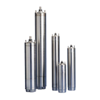
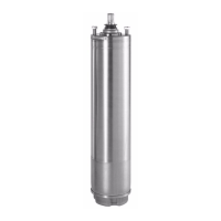
MS Motors
Shroud/Flow Inducer Sleeve/
Cooling Sleeve
On some installations it is necessary to use a shroud to
insure that all, or some portion of the produced fluid
pass by the motor in order to carry away the heat gener-
ated.
In some cases, the shroud is used to increase velocity
(create turbulent flow) in order to prevent the formation
of deposit and inhibit corrosion.
A shroudshould be used/ considered under the
following operating scenarios:
1. Top-feeding (cascading) wells can feed the water di-
rectly into the pump without its flowing past the mo-
tor if the well is not cased to below the motor, or
casing is perforated above the motor.
2. Flow may be inadequate when the motor is in a
large body of water or a casing much larger than the
motor, or if delivery is very low, or in sump/wet pit
tank applications.
3. If the groundwater is aggressive or contains
chloride, the corrosion rate will double for every
15°C (56F) increase in temperature between the
motor metallic housing and water. The motor hous-
ing is generally 5-15°C (41-56F)warmer than the
produced water. A cooling sleeve will therefore re-
duce the risk of motor corrosion by keeping the ex-
terior motor surface temperature lower during
operation.
4. If the well water contains a significant amount of
iron (iron bacteria), manganese and calcium. These
substances will be oxidized and deposited on the
motor surface. In case of low flow past the motor,
incrustation build-up forms a heat insulating layer of
oxidized minerals, which may result in hot spots in
the motor winding insulation. This temperature in-
crease may reach values, that impare the insulating
system, and consequently the motor life.
A cooling sleeve will insure turbulent flow past the
motor prohibiting incrustation build-up and optimize
cooling.
A cooling sleeve/shroud should be selected so as to
keep the maximum fluid velocity past the motor to 15
fps (12 fps by AWWA specs.).
At the higher velocities, erosion can be significantly
accelerated in the presence of abrasives and increase
intake losses can impare pump performance.
Head loss for various motor O.D. and casing/shroud
I.D. combinations are listed in Table 3, and should be
considered under marginal submergence and suction
conditions.
A fluid velocity of 3 fps is generally considered optimum
and 0.5 fps is the minimum cooling velocity value.
The actual fluid velocity past the motor can be calcu-
lated using the formula:
Velocity (past motor) = gpm/2.45 (ID casting)
2
- (OD motor)
2
.
where; Casing or shroud ID and motor OD values are in
inches, and velocity(past the motor is in fps.
(Table 3) Annular Space Head Loss (Hf) from Flow
Past Motor (ft. of Water)
Typical cooling sleeve/shroud configurations. The
motor shroud is generally of the next nominal diameter
of standard pipe larger than the motor or the pump,
depending on the shroud configuration used. The
tubular/pipe material can be plastic or thin walled steel
(corrosion resistant materials preferred). The cap/top
must accommodate power cable without damage and
provide a snug fit, so that only a very small amount of
fluid can be pulled through the top of the shroud. The fit
should not be completely water tight as ventilation is
often required to allow escape of the air or gas that
might accumulate. The shroud body should be stabi-
lized to prevent rotation and maintain the motor
centered within the shroud. The shroud length should
extend to a length of 1-2 times the shroud diameter
beyond the bottom of the motor when possible.
Shrouds are typically attached immediately above the
pump intake or at the pump/column correction.
A typical motor sleeve/shroud selection example is
sited below and illustrated in Figure 5:
Motor
(nominal)
4" 4" 4" 6" 6" 6"
Casing I.D. 4.25" 5" 6" 6" 7" 8"
gpm
25 0.3
50 1.2
100 4.7 0.3 1.7
150 10.2 0.6 0.2 3.7
200 1.1 0.4 6.3 0.5
250 1.8 0.7 9.6 0.8
300 2.5 1.0 13.6 1.2 0.2
400 23.7 2.0 0.4
500 3.1 0.7
600 4.4 1.0
Note: The tabulated friction loss values assume maximum motor length
for the specified nominal motor size and a smooth casing/sleeve ID, and
include entry and exit losses.
MS.book Page 21 Wednesday, January 26, 2005 3:25 PM
 Loading...