English (GB)
4
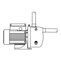
7.3 Setting the pressure switch
The cut-out pressure must be lower than the
maximum operating pressure of the pump and tank.
Remove the cover from the pressure switch to
access the adjusting screws. See fig. 1.
Fig. 1 Pressure switch
Setting the cut-out pressure
1. Turn screw (pos. A) clockwise to increase the
cut-out pressure. Turn it counter-clockwise to
reduce the cut-out pressure. The differential
pressure range remains unchanged.
2. Start the pump and check by reading the
pressure gauge whether the desired cut-out and
cut-in pressures have been obtained.
Setting the cut-in pressure
1. Turn screw (pos. B) clockwise to reduce the
cut-in pressure. Turn it counter-clockwise to
increase the cut-in pressure. The differential
pressure range is widened and narrowed
respectively.
2. Start the pump and check by reading the
pressure gauge whether the desired cut-out and
cut-in pressures have been obtained.
Repeat the procedure until the right cut-in and
cut-out pressures have been obtained.
8. Operation and maintenance
9. Frost protection
If there is a risk of frost, the tank and pump must be
drained.
10. Technical data
Ambient temperature
See nameplate.
Storage temperature
Minimum -10 °C.
Maximum +45 °C.
Liquid temperature
See nameplate.
System pressure
See nameplate.
Inlet pressure
At inlet pressures above 1.5 bar, the discharge
pressure must be at least 2.5 bar.
Supply voltage
See nameplate.
Insulation class
F.
Enclosure class
See nameplate.
Relative air humidity
Maximum 95 %.
Start/stop frequency
Maximum 100 per hour.
Warning
Switch off the power supply before
adjusting the pressure switch.
Fit the cover on the pressure switch before
you switch on the power supply to check
the cut-in and cut-out pressure.
TM01 6914 3799
Warning
Prior to start-up, the system should be
flushed through with clean water and
drained to remove possible impurities.