Troubleshooting 5‐9MN740
Fault Messages
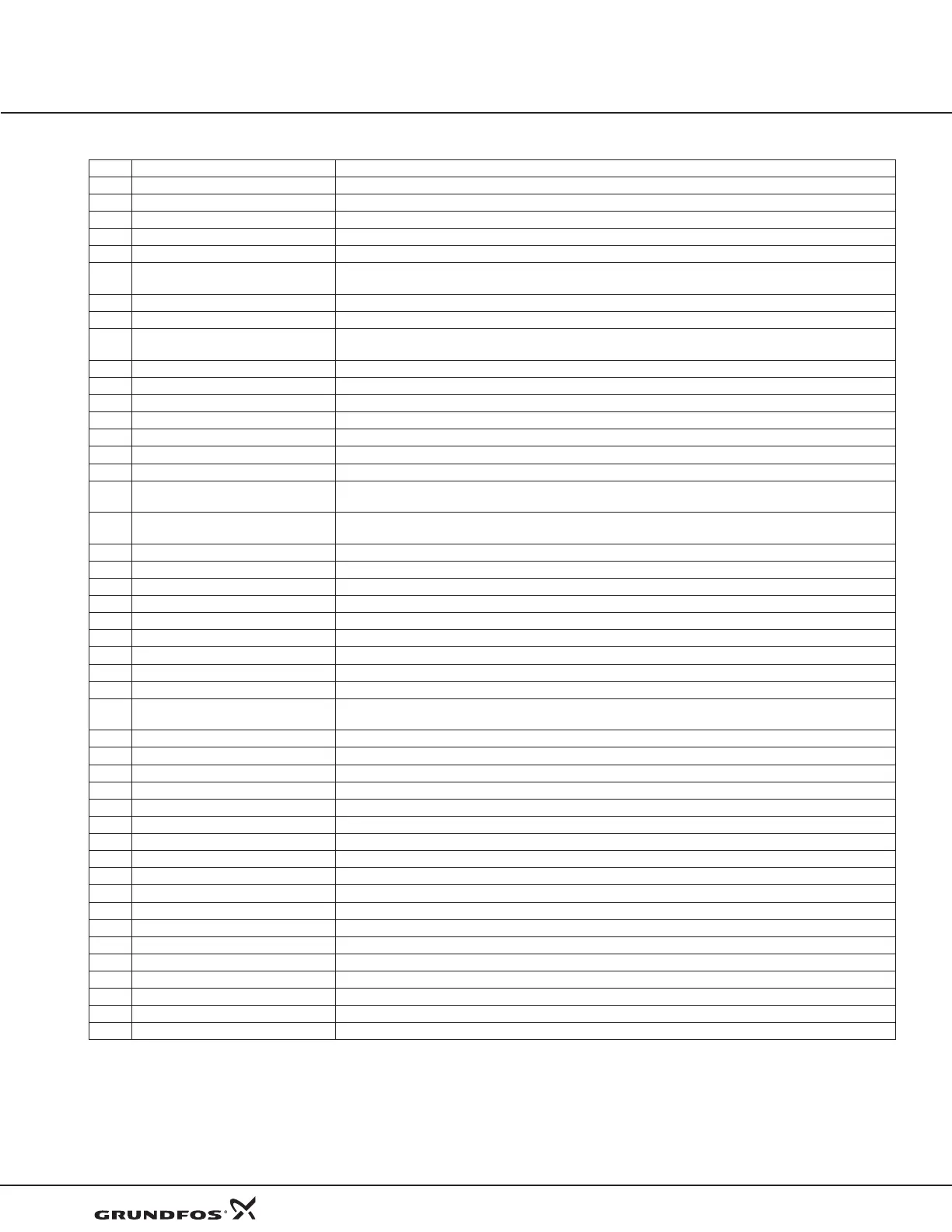
Table 5‐1 Fault Messages
Type Fault Message Display Description
No fault exists Control is operating properly, no faults recorded.
F Unknown system fault Reset the control. Restore parameter values to factory settings.
F Configuration Reset the control. Restore parameter values to factory settings.
F SPI timeout Serial Peripheral Interface (SPI) failure between control board and power board. Check connections.
F Param checksum Reset the control. Restore parameter values to factory settings.
F New base ID Changing the Power Base, Control board, or new firmware will most often cause this error.
Reset the control. Restore parameter values to factory settings.
F Over current Motor current exceeded peak limit. Check: motor connections, motor load, increase accel/decel times.
F Desaturation Output current exceeds desat limit. Check: motor for short circuit, motor load, increase accel/decel times.
F Ground fault Ground Fault detected (output current leakage to ground).
Disconnect motor, check motor for insulation leakage to ground.
F Logic supply Logic power supply failure detected.
F Power Base Fault Usually occurs with other faults. Fault detected in power base, see FPGA in event log trace.
F Low Initial BUS Bus volt less than 200/400/500V on 230/460/575V units at power up. Check: line volt, resistors on R1/ R2.
F Current Sense Occurs on power up, motor current sensor(s) out of tolerance.
F User ref Internal reference power supply out of tolerance.
F User 24 V 24V at J1-23 and J1-24 out of spec. Check 24V, if below, remove wiring from terminal strip, re-check.
F Current reference Reference volt for current readings out of tolerance.
F Overload - 1 minute Peak output current exceeded the 1 minute rating value. Check motor and wires, Level 2 Pk CUR Limit value,
Accel time or reduce motor load. Change Level 2 Drive Protect, Overload to “Foldback” and try again.
F Overload - 3 seconds Peak output current exceeded the 3 second rating value. Check motor and wires, Level 2 Pk CUR Limit value,
Accel time or reduce motor load. Change Level 2 Drive Protect, Overload to “Foldback” and try again.
F Motor Overload Motor current exceeded preset limits: 125% for 590 sec., 150% for 150 sec. or 200% for 50 sec.
F Following Error Speed error beyond Set Speed Band parameter value. Verify motor is not overloaded.
F DC Bus High DC Bus V over 405/810/1000V for 230V/460V/575V units. Check line volt, decel rates, resistor on R1/ R2.
F DC Bus Low DC Bus V below 220/440/550V for 230V/460V/575V units. Check line volt, B+ to B- voltage.
F Drive Over TEMP Heatsink temp exceeded 85/95qC. Verify ambient does not exceed 45qC. Clean fans and heatsink.
F Drive Low TEMP Heatsink temp is less than allowed (-10qC).
F External trip Connection at J2-16 is open and P2201 is set to ON.
F Torque Proving Failed to measure current in one or more motor phases. Check motor connections or open motor contacts.
F Regen R or PWR Excessive resistor power dissipation. Check resistor ratings, extend decel times, or add larger braking kit.
F EEPROM fault (Powerbase EE,
Control EE, Flt Log Mem, NV memory)
EE memory. Reset the control. Restore parameter values to factory settings.
F Internal Config Software boot error. Reset the control. Restore parameter values to factory settings.
F Dyn Brake Desat Dynamic braking current limit exceeded. Check for shorted braking resistor circuit.
A Line Loss All 3 input phases lost. Check input circuit breaker, fuses or input contacts.
A Phase Loss One input phase lost. Check input circuit breaker, fuses or input contacts.
F U Upper Fault Power transistor gate fault on T1.
F U Lower Fault Power transistor gate fault on T1.
F V Upper Fault Power transistor gate fault on T2.
F V Lower Fault Power transistor gate fault on T2.
F W upper fault Power transistor gate fault on T3.
F W lower fault Power transistor gate fault on T3.
F Ph 1 pulse Phase 1 (T1) curr limiting via pulse by pulse method; check motor: spiking loads, chattering contacts.
F Ph 2 pulse Phase 2 (T2) curr limiting via pulse by pulse method; check motor: spiking loads, chattering contacts.
F Ph 3 pulse Phase 3 (T3) curr limiting via pulse by pulse method; check motor: spiking loads, chattering contacts.
F Network Timeout Forced network fault. Possible reason: watchdog, timing, user control.
F Memory Option card problem, memory failure.
A Aux Filter Setup Filter Source should be set to Raw Speed when destination is set to Speed Loop.
F Power Base FPGA Power base communication loss or invalid FPGA version.
A Sel FB Source Encoder Source Not Selected/Feedback Board is absent. Choose the appropriate card for encoder feedback.
F = Fault, A = Alarm
 Loading...
