INSTALLATION PROCEDURES
2. Attach the Pump to the Pipe
A back-up wrench should be used when riser pipe is attached to the pump. The pump
should only be gripped by the flats on the top of the discharge chamber. Under no
circumstances grip the body of the pump, cable guard or motor. When tightened down,
the threaded end of the first section of the riser pipe or the nipple must not come in
contact with the check valve retainer in the discharge chamber of the pump. After the
first section of the riser pipe has been attached to the pump, the lifting cable or elevator
should be clamped to the pipe. Do not clamp the pump. When raising the pump and
riser section, be careful not to place bending stress on the pump by picking it up by
the pump-end only. It is recommended that plastic-type riser pipe be used only with the
smaller domestic submersibles. The manufacturer or representative should be contacted
to ensure the pipe type and physical characteristics are suitable for this use. Use the
correct joint compound recommended by the specific pipe manufacturer. Besides making
sure that points are fastened, we recommend the use of a torque arrestor when using
plastic pipe.
3. Lower the Pump Into the Well
Make sure the electrical cables are not cut or damaged in any way when the pump is
being lowered in the well. Do not use the power cables to support the weight of the pump.
To protect against surface water entering the well and contaminating the water source,
the well should be finished off above grade utilizing a locally approved well seal or
pitless adaptor unit. We recommend that steel riser pipes always be used with the larger
submersibles. A pipe thread compound should be used on all joints. Make sure that the
joints are adequately tightened in order to resist the tendency of the motor to loosen the
joints when stopping and starting.
The drop cable should be secured to the riser pipe at approximately every 10 ft/3 m to
prevent sagging, looping and possible cable damage. Nylon cable clips or waterproof tape
may be used. The cable splice should be protected by securing it with clips or tape just
above each joint.
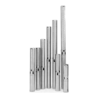
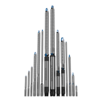
Figure 2 Figure 3
Check Valves: A check valve should always be installed at the surface of the well and one
at a maximum of 25 feet above static water level. In addition, for installations deeper than
200 feet, check valves should be installed at no more than 200 foot intervals.
IMPORTANT: Plastic pipe tends to stretch
under load. This stretching must be taken
into account when securing the cable to the
riser pipe. Leave three to four inches of slack
between clips or taped points. This tendency
for plastic pipe to stretch will also affect the
calculation of the pump setting depth. As a
general rule, you can estimate that plastic
pipe will stretch to approximately 2% of its
length. When plastic riser pipe is used, it is
recommended that a safety cable be attached
to the pump to lower and raise it. The
discharge chamber of GRUNDFOS 4-inch
submersibles is designed to accommodate
this cable. (See Figures 2 & 3.)
3