SAFETY WARNING
WARNING: Reduced risk of electric shock during operation of this pump requires the
provision of acceptable grounding. If the means of connection to the supply connected
box is other than grounded metal conduit, ground the pump back to the service by
connecting a copper conductor (at least the size of the circuit supplying the pump) to the
grounding screw provided within the wiring compartment.
NOTICE: This product is designes for pumping water only. Third party agency
evalustions are based on pumping water only.
Pre-Installation Checklist
1. Well Preparation
If the pump is to be installed in a new well then the well should be fully developed and bailed
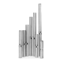
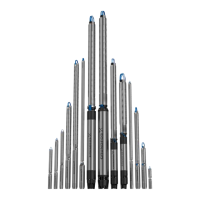
or blown free of cuttings and sand. The stainless steel construction of the GRUNDFOS
submersibles make it resistant to abrasion; however, no pump made of any material can
forever withstand the destructive wear that occurs when constantly pumping sandy water.
If this pump is used to replace an oil-filled submersible or oil-lubricated line-shaft turbine in
an existing well, the well must be blown or bailed clear of oil.
2. Make Sure You Have The Right Pump
Determine the maximum depth of the well, and the draw-down
level at the pump’s maximum capacity. Pump selection and
setting depth should be based on this data.
3. Pumped Fluid Requirements
CAUTION: Submersible well pumps are designed for pumping
clear, cold water; free of air or gases. Decreased pump
performance and life expectancy can occur if the water is not
cold, clear or contains air or gasses. Water temperature should
not exceed 102°F.
A check should be made to ensure that the installation depth of
the pump will always be at least three feet below the maximum
drawdown level of the well. The bottom of the motor should
never be installed lower than the top of the screen or within five
feet of the well bottom.
Ensure that the requirement for minimum flow past the motor is
met, as shown in the table below:
NOTES: For proper motor cooling, a flow inducer
or sleeve must be used if the water enters the
well above the motor or if there is insufficient
water flow past the motor. The minimum water
velocity past 4” motors is 0.25 feet per second.
Minimum Water Flow Requirements for
Submersible Pump Motors
MINIMUM CASING OR SLEEVE MIN. GPM FLOW
DIAMETER I.D. IN INCHES PASSING THE MOTOR
4-Inch 4 1.2
5 7
6 13
7 21
8 30
1