CCF 23 Allgemeiner Teil / General Section
GRUNDIG Service 1 - 7
4.Logik-Platte ausbauen
- Gehäuseoberteil abnehmen (siehe Pkt. 1).
- 2 Schrauben E und 2 Schrauben F (Fig. 3) herausdrehen.
- 5 Plattenhalter G (Fig. 3) ausrasten.
- Netzschalter in Stellung "Aus" bringen und danach den Netz-
schalterstößel H (Fig. 3) abziehen.
- Steckverbindungen lösen und Leiterplatte herausnehmen.
7. Cassettenfach-Deckelbremse ausbauen (Laufwerk A oder B)
- Gehäuseoberteil abnehmen (siehe Pkt. 1).
- Schraube M herausschrauben (Fig. 6 und 7).
- Bremse nach hinten herausnehmen.
Achten Sie auf die Cassettendeckel-Drehfeder I (Fig. 6).
7. Removing the Brake of the Cassette Compartment Lid
(Drive mechanism A or B)
- Remove the top of the cabinet (see para 1).
- Undo the screw M (Figs. 6 and 7).
- Take the brake out towards the rear.
Take care of the cassette lid torsion springs I (Fig. 6).
4. Removing the Logic Board
- Remove the top of the cabinet (see para 1).
- Undo 2 screws E and 2 screws F (Fig. 3).
- Unhook the 5 board holders G (Fig. 3).
- Set the power switch to "Off", then disengage the push-rod H of the
power switch (Fig. 3).
- Disconnect the plug-in connections and remove the circuit board.
2
1
4
3
Fig. 5
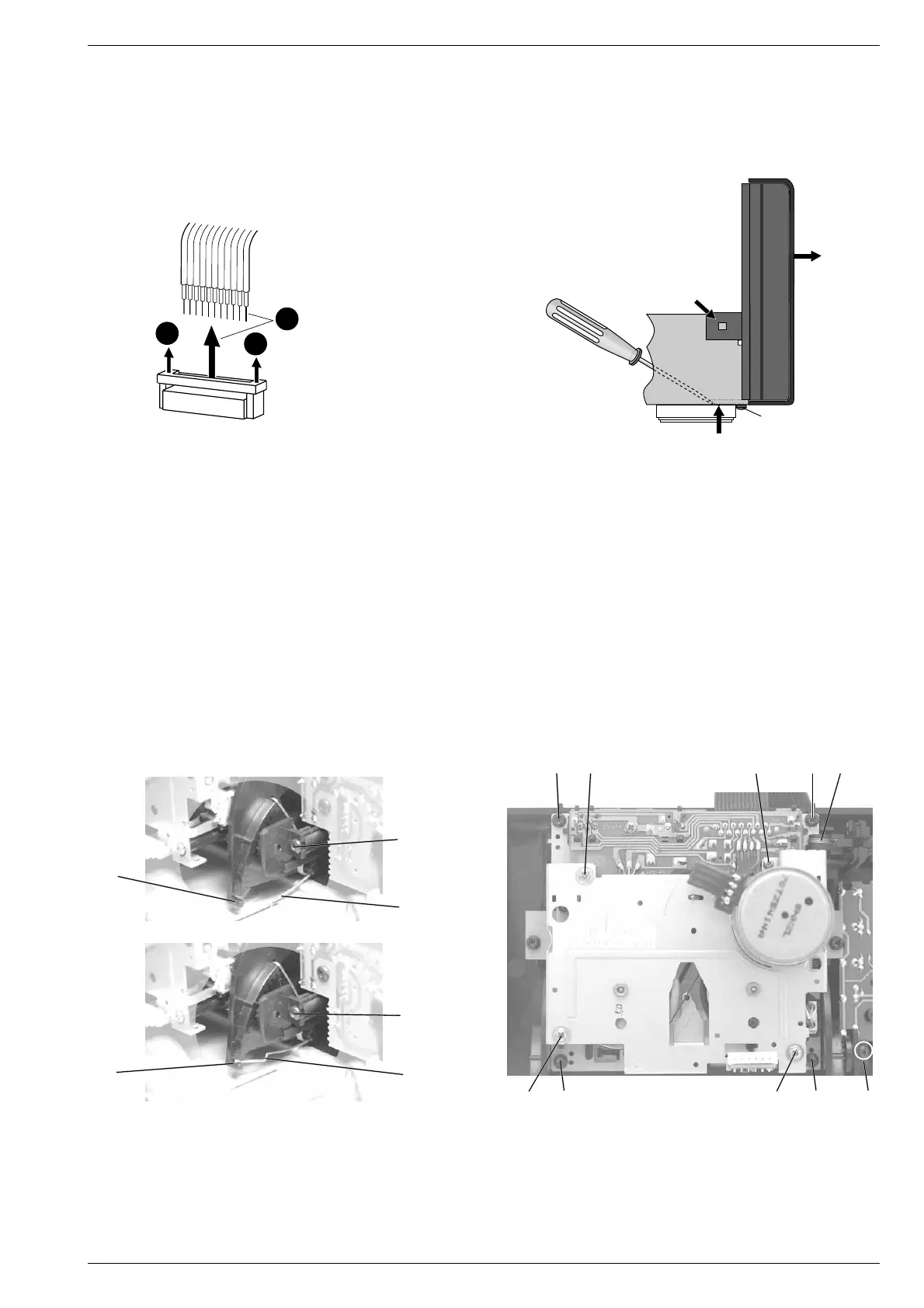
5. Frontblende (mit Leiterplatten) ausbauen
- Gehäuseoberteil abnehmen (siehe Pkt. 1).
- 2 Cassettendeckel-Drehfedern I über die Zapfen J (Fig. 6) ein-
hängen.
- Schraube 1 (Fig. 5) am Gehäuseboden herausdrehen.
- Laschen 2 links und rechts der Frontblende sowie 3 Haltezapfen 3
am Gehäuseboden ausrasten (Fig. 5).
- Netzschalter in Stellung "Aus" bringen und danach den Netz-
schalterstößel H abziehen (Fig. 3).
- Frontblende mit den Laufwerken vorsichtig nach vorne 4 abziehen
(Fig. 5).
- Bei Bedarf Steckverbindungen lösen.
6. Laufwerke ausbauen (A oder B)
- Gehäusefront abnehmen (siehe Pkt. 5).
- Drehfeder K aushängen (Fig. 7).
- 4 Schrauben L herausdrehen (Fig. 7).
- Laufwerk nach hinten herausnehmen.
5. Removing the Front Panel (with PCBs)
- Remove the top of the cabinet (see para 1).
- Attach the cassette lid torsion springs I to the lugs J (Fig. 6).
- Undo the screw 1 (Fig. 5) on the bottom of the cabinet.
- Disengage the lugs 2 on the left and right of the front panel and 3
prongs 3 on the bottom of the cabinet (Fig. 5).
- Set the power switch to "Off", then disengage the push-rod H of
the power switch (Fig. 3).
- Pull the front panel with the drive mechanisms carefully towards
the front 4 (Fig. 5).
- If necessary, disconnect the connectors.
6. Removing the Drive Mechanisms (A or B)
- Remove the front panel (see para 5).
- Unhook the torsion spring K (Fig. 7).
- Undo 4 screws L (Fig. 7).
- Take the drive mechanism out towards the rear.
Fig. 7
Fig. 6
J
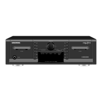
Fig. 4
Steckverbindungen
Connectors
P 502 - P 506
1
1
2
J
M
M
I
I
MLNL
N
K
LNNL
 Loading...