CCF 23 Allgemeiner Teil / General Section
GRUNDIG Service 1 - 9
12. Kupplungswechsel (17, 29)
- Laufwerkplatte ausbauen (siehe Pkt. 10).
- Schwungräder ausbauen (siehe Pkt. 11).
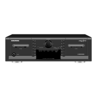
- Scheibe 102 und Riemenscheibe 23 abziehen (Fig. 10).
- Wickeldorn 9 aushebeln und abziehen (Fig. 14).
- Bei Bedarf das Zahnrad 21 abziehen (Fig. 13).
- Nehmen Sie die Kupplung nach hinten heraus.
12. Replacing the Clutch (17, 29)
- Remove the drive mechanism circuit board (see para 10).
- Remove the flywheel(s) (see para 11).
- Pull off the washer 102 and the pulley 23 (Fig. 10).
- Lift off and remove the spindle 9 (Fig. 14).
- If necessary pull off the gearwheel 21 (Fig. 13).
- Remove the clutch towards the rear.
13. Andruckrolle wechseln
- Laufwerk ausbauen (siehe Pkt. 6).
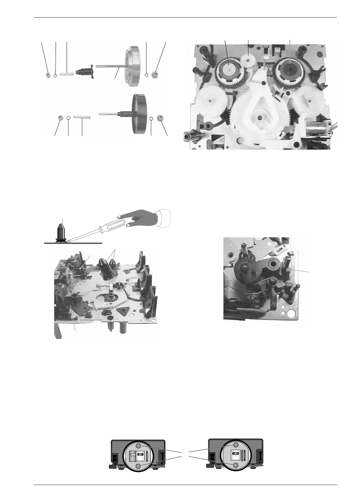
- Untere Drehfeder 65 bzw. 69 aushängen (Fig. 14).
- Rastnase T ausrasten und die Andruckrolle abziehen (Fig. 15).
- Beim Einbau sind die Federn wieder einzuhängen.
14. Tonkopf wechseln
- Laufwerk ausbauen (siehe Pkt. 6).
- Kopfleitungen aushängen.
- 2 Schrauben U herausdrehen und den Tonkopf herausnehmen
(Fig. 16).
- Kopfleitungen ablöten.
- Beim Einbau sind die Kopfleitungen wieder einzuhängen.
13. Replacing the Pressure Roller
- Dismantle the drive mechanism (see para 6).
- Unhook the lower torsion spring 65 or 69 (Fig. 14).
- Disengage the locking lug T and pull out the pressure roller
(Fig. 15).
- Refit the springs when mounting the new pressure roller.
14. Replacing the Sound Head
- Remove the drive mechanism (see para 6).
- Detach the head leads.
- Undo 2 screws U and remove the sound head (Fig. 16).
- Unsolder the head leads.
- Attach the head leads when re-assembling.
U
Fig. 16
3
3
445
3410373 33.1
25 103 72 103
33
26
44
3
5
3
32 103
27
Fig. 12
21
Fig. 14 Fig. 15
Deck B Deck A
9
Fig. 13
T
65
69
9
1729
 Loading...