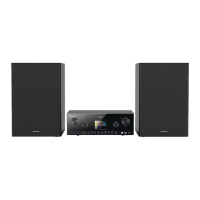
Allgemeiner Teil / General Section RCD 2000
1 - 2 GRUNDIG Service
Es gelten die Vorschriften und Sicherheitshinweise
gemäß dem Service Manual "Sicherheit", Material-
nummer 72010 800 0000, sowie zusätzlich die even-
tuell abweichenden, landesspezifischen Vorschriften!
The regulations and safety instructions shall be valid
as provided by the "Safety" Service Manual, part
number 72010 800 0000, as well as the respective
national deviations.
Table of Contents
Page
General Section........................... 1 - 2 … 1 - 19
Test equipment / aids................................................................ 1 - 2
Service Hint............................................................................... 1 - 3
Technical Data .......................................................................... 1 - 3
Disassembly Instructions .......................................................... 1 - 4
Operating Hints ....................................................................... 1 - 13
Adjustment Procedures................ 2 - 1 … 2 - 2
Circuit Diagrams and
Layout of PCBs ........................... 3 - 1 … 3 - 27
Wiring Diagram ......................................................................... 3 - 1
Circuit Diagrams
CD Control Board .................................................................. 3 - 4
CD Servo Board .................................................................... 3 - 8
AF Board ............................................................................. 3 - 14
Tuner Board ........................................................................ 3 - 16
Display Board ...................................................................... 3 - 20
Switch Boards ..................................................................... 3 - 22
Power Supply ...................................................................... 3 - 25
Layout of PCBs
CD Control Board .................................................................. 3 - 6
CD Servo Board .................................................................. 3 - 12
AF Board ............................................................................. 3 - 13
Tuner Board ........................................................................ 3 - 18
Display Board ...................................................................... 3 - 19
Switch Boards ..................................................................... 3 - 23
Mains Connection Board ..................................................... 3 - 25
Display .................................................................................... 3 - 26
IC Block Diagrams .................................................................. 3 - 27
Exploded Views and
Spare Parts List............................. 4 - 1 … 4 - 6
Inhaltsverzeichnis
Seite
Allgemeiner Teil .......................... 1 - 2 … 1 - 13
Messgeräte / Messmittel ........................................................... 1 - 2
Servicehinweis .......................................................................... 1 - 3
Technische Daten ..................................................................... 1 - 3
Ausbauhinweise ........................................................................ 1 - 4
Bedienheinweise ....................................................................... 1 - 7
Abgleichvorschriften .................... 2 - 1 … 2 - 2
Schaltpläne und
Druckplattenabbildungen........... 3 - 1 … 3 - 27
Verdrahtungsplan...................................................................... 3 - 1
Schaltpläne
CD-Control-Platte .................................................................. 3 - 4
CD-Servo-Platte .................................................................... 3 - 8
NF-Platte ............................................................................. 3 - 14
Tuner-Platte ........................................................................ 3 - 16
Display-Platte ...................................................................... 3 - 20
Tasten-Platten ..................................................................... 3 - 22
Netzteil ................................................................................ 3 - 25
Druckplattenabbildungen
CD-Control-Platte .................................................................. 3 - 6
CD-Servo-Platte .................................................................. 3 - 12
NF-Platte ............................................................................. 3 - 13
Tuner-Platte ........................................................................ 3 - 18
Display-Platte ...................................................................... 3 - 19
Tasten-Platten ..................................................................... 3 - 23
Netzanschluß-Platte ............................................................ 3 - 25
Display .................................................................................... 3 - 26
IC-Innenbeschaltungen ........................................................... 3 - 27
Explosionszeichnungen
und Ersatzteilliste ......................... 4 - 1 … 4 - 6
Allgemeiner Teil
Messgeräte / Messmittel
Mess-/Wobbelsender Oszilloskop
Digital-Voltmeter NF-Voltmeter
Klirrfaktor-Messgerät
Beachten Sie bitte das GRUNDIG Messtechnik-Programm, das Sie
unter folgender Adresse erhalten:
General Section
Test Equipment / Aids
Standard/sweep generator Oscilloscope
Digital voltmeter AF voltmeter
Distortion meter
Please note the Grundig Catalog "Test and Measuring Equipment"
obtainable from:
GRUNDIG Instruments
Test- und Messsysteme GmbH
Würzburger Str. 150
D 90766 Fürth/Bay
Tel. 0911/703-4118
Fax 0911/703-4130
eMail: instruments@grundig.de;
Internet: http://www.grundig-instruments.de
 Loading...