RCD 2000 Allgemeiner Teil / General Section
GRUNDIG Service 1 - 5
h
M
M
L
i
N
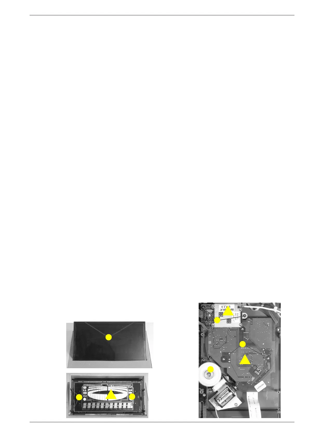
Fig. 4
Fig. 5 Fig. 6
4. Tuner-Platte c ausbauen
- Boden entfernen (Pkt. 1).
- 2 Schrauben G herausschrauben und Tuner-Platte herausnehmen
(Fig. 3).
- Kabelbinder und Steckverbinder nach Bedarf öffnen.
5. Audio Funk-Modul d ausbauen
- Boden entfernen (Pkt. 1).
- Schraube H herausschrauben und Funkmodul herausnehmen
(Fig. 3).
- Kabelbinder und Steckverbinder nach Bedarf öffnen.
6. Daten Funk-Modul e ausbauen
- Boden entfernen (Pkt. 1).
- 2 Schrauben I herausschrauben und Funkmodul herausnehmen
(Fig. 3 / Fig. 6).
- Kabelbinder und Steckverbinder nach Bedarf öffnen.
7. Netztrafo f ausbauen
- Boden entfernen (Pkt. 1).
- 4 Schrauben J herausschrauben und Netztrafo herausnehmen
(Fig. 3).
- Kabelbinder und Steckverbinder nach Bedarf öffnen.
8. Netzanschluss-Platte g ausbauen
- Boden entfernen (Pkt. 1).
- 4 Schrauben K herausschrauben und Netzanschluss-Platte her-
ausnehmen (Fig. 3).
- Kabelbinder und Steckverbinder nach Bedarf öffnen.
9. Display-Platte h ausbauen
- Boden entfernen (Pkt. 1).
- 2 Rastnasen L ausrasten und Displayabdeckung abnehmen
(Fig. 4).
- 4 Schrauben M herausschrauben und Display-Platte herausneh-
men (Fig. 5).
- Kabelbinder und Steckverbinder nach Bedarf öffnen.
10. CD-Laufwerk und CD-Servo-Platte i ausbauen
- CD-Control-Platte (Pkt. 2) und Daten Funk-Modul (Pkt. 6) ausbau-
en.
- 3 Schrauben N herausschrauben und CD-Logik-Platte zusammen
mit dem CD-Laufwerk herausnehmen (Fig. 6).
- Kabelbinder und Steckverbinder nach Bedarf öffnen.
11. Tastenplatte links j ausbauen
- Netztrafo ausbauen (Pkt. 7).
- 4 Schrauben O herausschrauben und Tastenplatte herausnehmen
(Fig. 7).
- Kabelbinder und Steckverbinder nach Bedarf öffnen.
12. Tastenplatte rechts k ausbauen
- Audio Funk-Modul ausbauen (Pkt. 5).
- 6 Schrauben P herausschrauben und Tastenplatte herausnehmen
(Fig. 8).
- Achtung: Unter den 4 Tasten Q befinden sich Federn!
- Kabelbinder und Steckverbinder nach Bedarf öffnen.
13. Linke Tasten ausbauen
- Tastenplatte links ausbauen (Pkt. 11).
- 4 Schrauben R herausschrauben und Tasten herausnehmen
(Fig. 7).
I
4. Removing the Tuner Board c
- Remove bottom (para 1).
- Undo 2 screws G and remove the Tuner Board (Fig. 3).
- Open cable supports and connectors if necessary.
5. Removing the Audio RF Module d
- Remove bottom (para 1).
- Undo screw H and remove the Audio RF Module (Fig. 3).
- Open cable supports and connectors if necessary.
6. Removing the Data RF Module e
- Remove bottom (para 1).
- Undo 2 screws I and remove the Data RF Module (Fig. 3 / Fig. 6).
- Open cable supports and connectors if necessary.
7. Removing the Mains Transformer f
- Remove bottom (para 1).
- Undo 4 screws J remove the Mains Transformer (Fig. 3).
- Open cable supports and connectors if necessary.
8. Removing the Mains Con Board g
- Remove bottom (para 1).
- Undo 4 screws K and remove the Mains Con Board.
- Open cable supports and connectors if necessary.
9. Removing the Display Board h
- Remove bottom (para 1).
- Undo 2 catches L and remove the Display cover (Fig. 4).
- Undo 4 screws M and remove the Display Board (Fig. 5).
- Open cable supports and connectors if necessary.
10. Removing the CD Drive and the CD Servo Board i
- Remove CD Control Board (para 1) and Data RF Module (para 6).
- Undo 3 screws N and remove the CD Servo Board together with the
CD Drive (Fig. 6).
- Open cable supports and connectors if necessary.
11. Removing the Switch Board left j
- Remove the Mains Transformer (para 7).
- Undo 4 screws O and remove the Switch Board (Fig. 7).
- Open cable supports and connectors if necessary.
12. Removing the Switch Board right k
- Remove the Audio RF Module (para 5).
- Undo 6 screws P and remove the Switch Board (Fig. 8).
- Attention on the 4 springs below the buttons Q.
- Open cable supports and connectors if necessary.
13. Removing the left buttons
- Remove the Switch Board left (para 11).
- Undo 4 screws R and remove the buttons (Fig. 7).
e
T
 Loading...