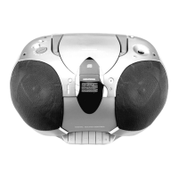
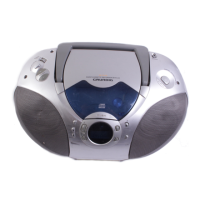
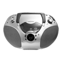
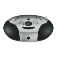
RR 710 CD / RR 750 CD Allgemeiner Teil / General Section
GRUNDIG Service 1 - 9
2
O
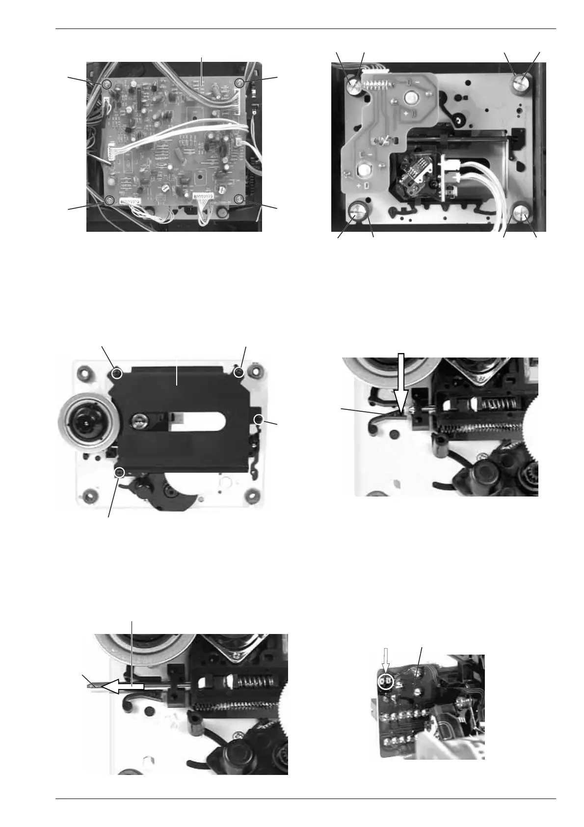
Achtung beim Einbau einer neuen Lasereinheit:
Die Laserdiode ist gegen statische Aufladung beim Transport kurz-
geschlossen. Nach dem Einbau und Anschluß der Lasereinheit muß
die Kurzschlußlötstelle G (Fig. 10) auf der Laseranschlußplatte
aufgelötet werden.
Verstellen Sie nicht den Regler für die Laserstromeinstellung!
Der Laserstrom wurde werkseitig eingestellt.
Attention when fitting the new pick-up:
The laser diode is short-circuited for protection against static charges
during transportation. After fitting the laser unit the soldered short
circuit G (Fig. 10) on the laser connection board must be opened.
Do not turn the variable resistor (laser power adjustment).
The laser current is pre-set at the factory.
5. Removing the Laser Pick-Up
- Remove the CD drive mechanism (see para 4).
- Undo 4 screws L and remove the cover plate M (Fig. 7).
- Push the locking device N carefully in the direction of the arrow 1
(Fig. 8).
- Move the guide rail O in the direction of arrow 2 and remove the
laser pick-up (Fig. 9).
5. Lasereinheit ausbauen
- CD-Laufwerk ausbauen (siehe Pkt. 4).
- 4 Schrauben L herausdrehen und Abdeckblech M abnehmen
(Fig. 7).
- Sperre N vorsichtig in Pfeilrichtung 1 drücken (Fig. 8).
- Führungsstange O in Pfeilrichtung 2 schieben und Lasereinheit
abnehmen (Fig. 9).
N
1
Fig. 7
L
ML
Fig. 10Fig. 9
G
Laseranschlußplatte
Laser PCB
Fig. 8
Fig. 6
Fig. 5
L
L
I
K
J
I
IJ K I
CD-Leiterplatte
CD PCB
HH
H
H