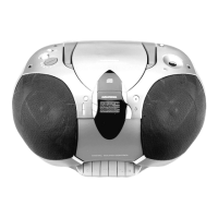
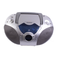
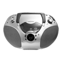
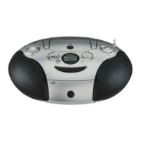
Allgemeiner Teil / General Section RR 710 CD / RR 750 CD
1 - 8 GRUNDIG Service
Disassembly Instructions
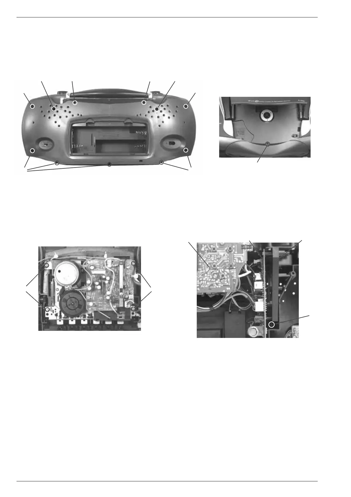
1. Removing the Cabinet Front
- Undo 2 screws A (long) and 7 screws B (short) (Fig. 1).
- Undo the screw C in the CD compartment (Fig. 2).
- Remove the front of the cabinet towards the front.
- Disconnect the plug-in connections if necessary.
Fig. 3 Fig. 4
3. Removing the Chassis, (Fig. 1 and 4)
- Remove the cabinet front (see para 1).
- Undo 2 screws E (Fig. 1).
- Undo the screw F (Fig. 4).
- Remove the chassis towards the front (with volume control PCB,
tuner PCB, control PCB, CD unit).
- Disconnect the plug-in connections if necessary.
4. Removing the CD Mechanism
When removing the Laser pick-up, the pick-up PCB must be provided
with a protective soldered joint G before unplugging the connec-
tors to avoid damage to the Laser diode by static charges (Fig. 10).
- Remove the chassis (see para 3).
- Undo 4 screws H (Fig. 5).
- Unplug the connectors from the CD circuit board.
- Take out the CD circuit board.
- Undo 4 screws I (Fig. 6).
- Remove the CD mechanism.
Take care of the buffers J (black) and K (blue) Fig. 6. The buffer
pressure is different (black = stronger, blue = weaker).
3. Chassis ausbauen, (Fig. 1 und 4)
- Gehäusevorderteil abnehmen, (siehe Pkt. 1).
- 2 Schrauben E herausdrehen (Fig. 1).
- Schraube F herausdrehen (Fig. 4).
- Chassis (mit Lautstärkereglerplatte, Tunerplatte, Bedienplatte, CD-
Teil) nach vorne herausnehmen.
- Bei Bedarf Steckverbindungen abziehen.
4. CD-Laufwerk ausbauen
Bei Ausbau der CD-Lasereinheit muß vor Abziehen der Steckver-
bindungen eine Schutzlötstelle G auf der Leiterplatte der Laser-
einheit angebracht werden, um eine Zerstörung der Laserdiode
durch statische Aufladung zu vermeiden (Fig. 10).
- Chassis ausbauen (siehe Pkt. 3).
- 4 Schrauben H (Fig. 5) herausdrehen.
- Steckverbindungen von der CD-Leiterplatte abziehen.
- CD-Leiterplatte abnehmen.
- 4 Schrauben I herausdrehen (Fig. 6).
- CD-Laufwerk herausnehmen.
Achten Sie dabei auf die Puffer (Fig. 6) J (schwarz) und K (blau).
Diese Puffer haben einen unterschiedlichen Auflagedruck
(schwarz = stärker, blau = schwächer).
Ausbauhinweise
1. Gehäusevorderteil abnehmen
- 2 Schrauben A (lang) und 7 Schrauben B (kurz) herausdrehen
(Fig. 1).
- Schraube C im CD-Fach (Fig. 2) herausdrehen.
- Gehäusevorderteil nach vorne abnehmen.
- Bei Bedarf Steckverbindungen abziehen.
E
A
A
E
C
B
B
BB
DD
Bedienplatte
Control PCB
Chassisrahmen
Chassis frame
F
Tunerplatte
Tuner PCB
Fig. 2
2. Cass.-Laufwerk ausbauen, (Fig. 3)
- Gehäusevorderteil abnehmen (siehe Pkt. 1).
- 4 Schrauben D herausdrehen.
- Cassettenfachdeckel durch Drücken der Taste STOP/EJECT
öffnen.
- Laufwerk herausnehmen.
- Eventuell Kabelbinder lösen.
2. Dismantling the Cassette Drive Mechanism, (Fig. 3)
- Remove the cabinet front (see para 1).
- Undo 4 screws D.
- Open cassette compartment lid by pressing the buttton STOP/
EJECT.
- Take out the cassette drive mechanism.
- Eventually loosen the cable ties.
Fig. 1