Allgemeiner Teil / General Section STR 6000
1 - 8 GRUNDIG Service
Operating Hints
This chapter contains excerpts from the operating instructions. For further particulars please refer to the appropriate user instructions the part number
of which is indicated in the relevant spare parts list.
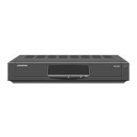
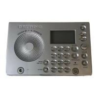
The Receiver at a Glance
Front panel
❒
Displays
Numeric Indicates the number of the selected programme position.
display When the Timer is activated, »t« appears instead of a pro-
gramme number.
Red LED Lights up when the receiver is switched to stand-by.
Green LED Ligths up when the integrated Timer is activated or switched
to stand-by, i.e. it is waiting for the start time.
❒
Keys
8 Stand-by key. Switches the receiver to stand-by and from
stand-by back to the last selected programme position
(”last station memory”).
w Selects step by step the next higher programme position.
q Selects step by step the next lower programme position.
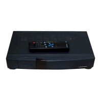
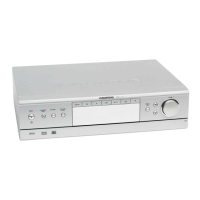
Rear panel
MAINS INPUT Connector for plug-in mains cord.
CH.ADJ. Modulator output tuning control (channels 30 to 45)
TSG Test signal generator switch (for connecting a TV set
or video recorder via the modulator output).
AERIAL Terrestrial aerial input (VHF/UHF)
TV/VCR Modulator output (VHF/UHF)
AUDIO OUT Audio cinch connector, left/right stereo channels for
hifi system.
TV Euroconnector for TV set
VCR Euroconnector for video recorder (VCR)
DECODER Euroconnector for external decoder
LNC Satellite dish aerial input
The type plate is to be found on the bottom of the housing.
6
The Receiver at a Glance
CH.ADJ.
TSG
AERIAL
ASSEMBLED IN U.K.
VCR
DECODER
HAZARD-LIVE PARTS
DO NOT REMOVE COVERS
40W MAX.
50 Hz
230V
TV
300mA DC
14V/18V
LNC
INPUT
MAINS
TV /VCR
R
L
AUDIO
OUT
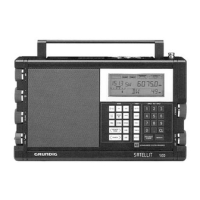
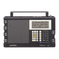
Remote control keys
“
8 Swiches the receiver to stand-by and from stand-by back to
the last selected programme position (”last station memory”).
“a Sound mute key. »STUMM« (mute) appears on the picture
screen.
“0 … “ 9 Programme selection (also from stand-by) and data entry in
menu mode.
“TV/SAT Certain TV sets switch automatically to AV mode when
putting the SAT receiver into operation. Press this key if you
wish to switch back to terrestrial mode.
“FAV Keys for toggling between favourite mode (the
M
“
N
“
keys
switch only to pre-set satellite programmes, non pre-set
programmes are skipped) and normal mode (the
M
“
N
“
keys select the next higher or lower programme position,
respectively).
M
“
N
“
Step-by-step programme selection.
In menu mode: menu item selection.
T
“
Z
“
In menu mode: value modification.
“´ Press 1x: time display on the picture screen.
Press 2x: TIMER menu display on the picture screen.
When in the TIMER menu: exit.
When you are in a different menu, this will be closed and the
time displayed instead.
“$ When in the menus: blue background on and off.
“VIDEO Opens/closes the VIDEO menu (when you are in a different
menu, this will be closed and the VIDEO menu opened).
“AUDIO Opens/closes the AUDIO menu (when you are in a different
menu, this will be closed and the audio menu opened).
“SYSTEM Opens/closes the SYSTEM menu (when you are in a different
menu, this will be closed and the system menu opened).
Remote Control Unit
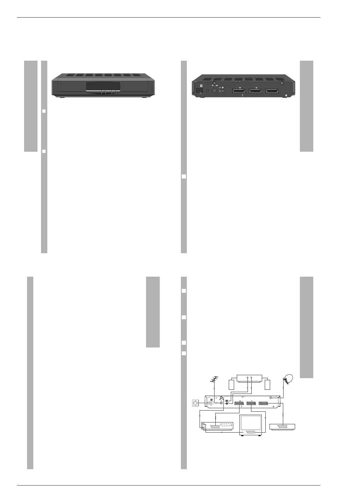
How to connect the satellite aerial
Connect the cable of your satellite aerial to the LNC input on the rear panel
of the receiver.
Connection via a EURO-AV cable
You get the best picture quality if you use EURO-AV cables (”Euroconnec-
tors”) for connecting your SAT receiver with a TV set, video recorder and
decoder as shown in the Figure. If this should not be possible, follow the
procedure specified in the paragraph ”Connection via the modulator out-
put”.
When playing back video recordings, the signals from the video recorder
are looped through the satellite receiver to the TV set.
If you wish to receive also terrestrial programmes, connect the terrestrial
aerial cable to the AERIAL socket on the rear of the receiver. The signal for
the video recorder and the TV set is available at the TV/VCR modulator out-
put of the receiver.
2
6
1
1
Connections and Installation
CH.ADJ.
TSG
AERIAL
ASSEMBLED IN U.K.
VCR
TV
DECODER
300mA DC
14V/18V
LNC
HAZARD-LIVE PARTS
DO NOT REMOVE COVERS
R
L
TV /VCR
INPUT
MAINS
40W MAX.
50 Hz
230V
AUDIO
OUT
VCR
Decoder
LR
HiFi-Amplifier
t
t
 Loading...