EasyManua.ls Logo

Grundig Yacht Boy P 2000 User Manual

Grundig Yacht Boy P 2000
20 pages
To Next Page IconTo Next Page
Page #1 background imageLoading...
Page #1 background image
M 7-C / M 17-C / M 27-C Allgemeiner Teil / General Section
GRUNDIG Service 1 - 1
Service Manual
Audio
Yacht Boy P 2000
Zusätzlich erforderliche
Unterlagen für den Komplettservice
Additionally required
Service Manuals for the Complete Service
Service
Manual
Service
Manual
Btx * 32700 #
Sachnummer
Part Number 72010-757.00
Änderungen vorbehalten
Subject to alteration
Printed in Germany
VK231 1197
Yacht Boy
P 2000
Sach-Nr./Part No.
72010-757.00
Sicherheit
Safety
Sach-Nr./Part No.
72010-800.00
Grundig Service
Hotline Deutschland...
TV/SAT
VCR/LiveCam
HiFi/Audio
Car Audio
Telekommunikation
Fax:
0180/52318-41
0180/52318-42
0180/52318-43
0180/52318-44
0180/52318-45
0180/52318-51
...Mo.-Fr. 8.00-16.30 Uhr
Ersatzteil-Bestellannahme:
0180/52318-40
0180/52318-50
Telefon:
Fax:
Technik:
D
E
S
I
G
N
B
Y
F
.
A
.
P
O
R
S
C
H
E
RADIO/BUZZ
RESET
SLEEP
METER
POWER
LOCK
M
H
LIGHT
3
2
1
4
5
6
9
8
7
0
FREQ
MODE
ALARM
MEMO
TIME SET
Question and Answer IconNeed help?

Do you have a question about the Grundig Yacht Boy P 2000 and is the answer not in the manual?

Grundig Yacht Boy P 2000 Specifications

General IconGeneral
TypePortable Radio
Frequency RangeFM: 87.5-108 MHz
BandsSW, FM
Power Supply4 x AA batteries or AC adapter
Headphone JackYes
AntennaTelescopic
DisplayAnalog
SpeakerBuilt-in

Summary

Service Manual

Operating Instructions

Wecker

Instructions on setting and using the alarm feature of the device.

Radio Reception

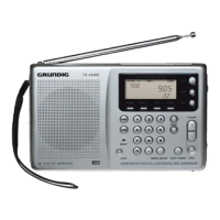
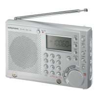
General instructions for receiving radio broadcasts on various bands.

Tuning to a station

Methods for tuning into specific radio stations, including manual and automatic.

Preset radio stations

Procedures for programming and recalling stored radio stations.

Disassembly Instructions

Rear Panel

Instructions for removing the rear casing of the device.

Chassis

Steps to remove the main chassis from the device housing.

Main Board

Procedure for removing the main circuit board from the chassis.

Operating Board

Steps to remove the control panel board from the device.

Alignment

AM IF Alignment

Calibration steps for the AM Intermediate Frequency stage.

FM IF Alignment

Calibration steps for the FM Intermediate Frequency stage.

MW Oscillator VCO Alignment

Tuning the Medium Wave oscillator circuit for correct operation.

SW1 Oscillator VCO Alignment

Tuning the Short Wave 1 oscillator circuit.

SW2 Oscillator VCO Alignment

Tuning the Short Wave 2 oscillator circuit.

IC Block Diagrams

Related product manuals