23
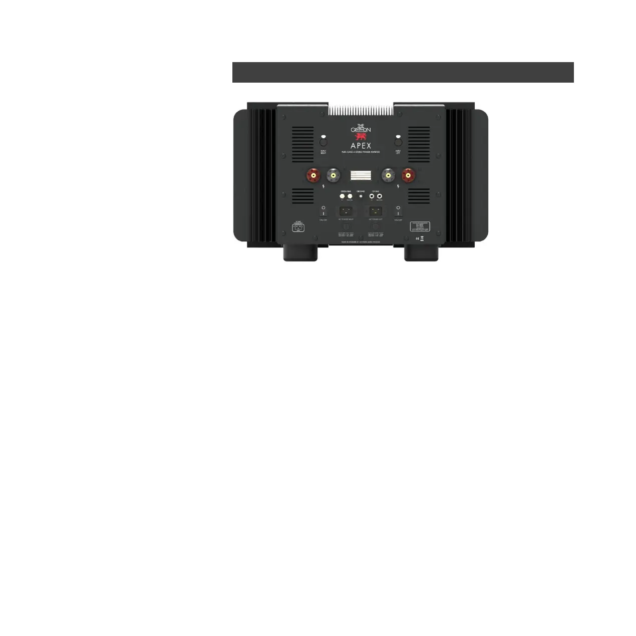
INPUT RIGHT / INPUT LEFT
Right and left stereo channel balanced XLR* inputs.
Right and left stereo channel loudspeaker outputs
Accepts bare wire, 4mm banana plugs, spade lugs (up to 17mm wide, min. 6,5mm between
lugs) or any combination thereof. Positive (red) is hot, negative (black) is neutral.
GREEN BIAS IN and PASS-THRU: Please refer to the description in the chapter: "Green Bias".
Also for switching the Apex between STB (Standby) and ON when connected to a Gryphon
preamplifier via Green Bias control link.
GROUND: Binding post for chassis ground.
12V LINK INPUT and PASS-THRU: For switching the Apex between STB (Standby) and ON
when connected to a unit with compatible link output.
AC mains power switches: NOTE: BOTH main switches must be switched ON before the
amplifier will be operational.
Mains input sockets: Two IEC Appliance inlets C20 (for power cords with IEC C19 receptacle)
Main fuse holders: 100-120Vac: T16A / 250V 220-240Vac: T8A / 250V
*) All Gryphon products follow the AES
standard for balanced connections:
1. Ground 2. Positive 3. Negative
Gryphon recommends the use of dedicated
balanced interconnect cables. Avoid the use
of RCA-to-XLR adaptors as they will degrade
system performance.