EasyManua.ls Logo

GSD Digital Keypad User Manual

GSD Digital Keypad
8 pages
To Next Page IconTo Next Page
Page #1 background imageLoading...
Page #1 background image
Installation & User Manual V1.1
No.1 Turnpike Business Park,
Ballymount,
Dublin 22, Ireland.
Telephone: +353 1 524 2691.
Fax: +353 1 4430 430.
2
Initial Setup
Contents
4
Installation Diagrams
6
Wiring Diagrams
12
Enrolling Door Controls
Wi-Smart
Other products from GSD
standalone products
GSD also offers fully functional standalone door controls for less complex door
management. This attractive design, with modern aesthestics, will complement
any building
- GSD Digital Keypad
- GSD Proximity Switch
- GSD Pin&Prox Switch
- GSD Biometric Switch
Features:
50 users
Access control
Door Monitoring
Manager User
Fire and Intruder alarm interface
Backlighting
Tamper resistant
5 amp relays
Indoor or outdoor use
Robust polycarbonate housing with stainless steel keys
Mounts onto a standard electrical back box
Question and Answer IconNeed help?

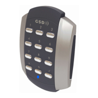
Do you have a question about the GSD Digital Keypad and is the answer not in the manual?

GSD Digital Keypad Specifications

General IconGeneral
IP RatingIP65
Output FormatWiegand
Current Consumption100mA
Number of Digits4 digits
Communication InterfaceRS485

Summary

Initial Setup

Initial Installation

Factory defaulting restores settings and unenrols the Door Control. It will then scan and enrol onto a GSD controller.

Wiring Diagrams

Wiring Diagram - Smart Slave

Details wiring connections for a Smart Slave device, including power, buzzer, LEDs, and data outputs.

Restoring Factory Settings: Wi-Smart

Provides steps to restore factory settings using programming cards for the Wi-Smart system.

Adding a Programming Card

Instructions on how to add a new programming card to the Door Control unit.

Factory Default PIN codes

Lists the default Engineer and User PIN codes for the Door Control system.

Installation Diagrams

Surface Mounting

Explains surface mounting the Door Control using a collar and security screws.

Assigning a Door Address on Wireless Network

Steps to assign a door address to a Door Control unit on a wireless network.

Assigning a Door Address on a Wired 485 Network

Steps to manually assign door addresses to Door Controls on a wired 485 network.

Enrolling Door Controls

Adding Door Controls

Describes the process of adding new door controls to the GSD system via the software interface.

Flush Mounting

Details flush mounting the Door Control to an electrical pattress box using security screws.

Wiring Diagrams

Wiring Diagram with Slave Reader

Illustrates wiring connections for a system with a slave reader, including inputs and outputs.

Wiring Diagram with External IP3 Function

Shows wiring for a system with an external IP3 function, detailing connections for fire alarm and break glass.

Wiring Diagrams

Wiring Diagram with Interlock Connection

Depicts wiring for interlock connections between two doors, including fire alarm and break glass inputs.

Wiring Diagram with Intruder Alarm Panel

Details wiring for connecting an Intruder Alarm Panel, including arm output and alarm input connections.

Wiring Diagrams

Wiring Diagram with Slave Reader

Provides a detailed wiring diagram for a system incorporating a slave reader, showing all connection points.