4. Installation
PNEG-2381 2000 Series U-Trough Bin Sweep Auger Unload System (72' - 78') 41
Measuring Misalignment
Gates engineers say the best tool for measuring misalignment is a laser alignment device. However, when
one is unavailable, the next best tool is a straightedge such as a long level, a strip of extruded aluminum,
or a ruler, depending on the center distance of the drive. The laser tool and straightedge are used to
project the orientation of one sheave or sprocket face with respect to the other.
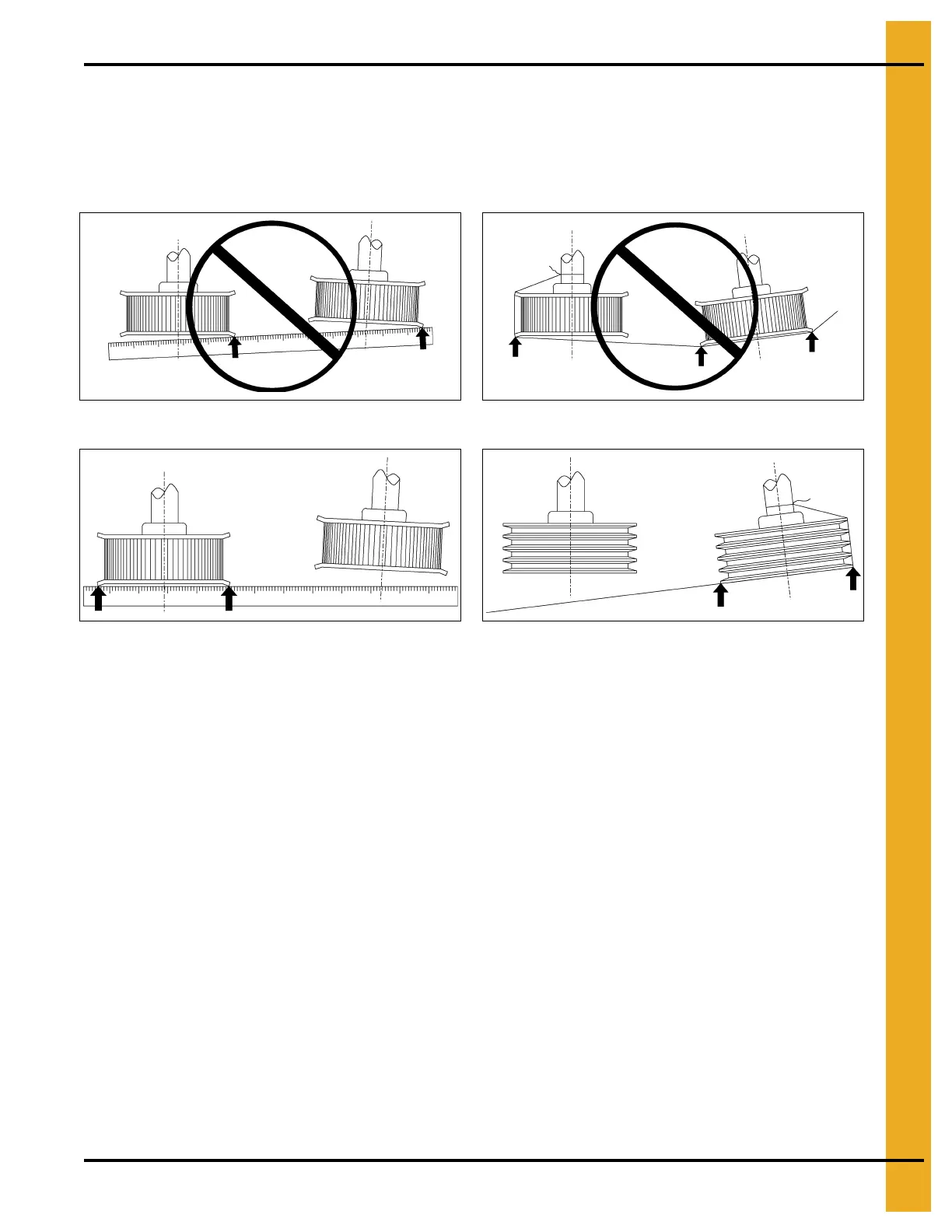
Figure 4BF Incorrect
Figure 4BG Correct
Figure 4BH Incorrect
Figure 4BI Correct
When preparing to measure parallel misalignment, the maintenance technician must first verify that the
edges of both sheaves and sprockets are of equal thickness, or quantify the difference in thickness. It is
important to align the sheave grooves or sprocket faces directly in line with one another, rather than just
the outside surfaces of the sheaves or sprockets (flanges). It may be necessary to mount sheaves or
sprockets with the outside surfaces offset with respect to one another in order to properly align the grooves
or sprocket faces.
Sprocket flanges should also be inspected to be sure that they run true. A bent flange could result in
erroneous measurements if the laser tool or straightedge rests against the outside edge of the damaged
flange during the inspection process.
To determine how much misalignment is acceptable and at what point it becomes excessive, the
alignment must first be measured, quantified, and then compared to the belt manufacturer’s
recommendations for the particular type of belt. These recommendations can be found in drive design
manuals.
Quantifying Misalignment
Misalignment can either be quantified mathematically, or be compared to some general rules of thumb for
quicker and easier results. While using a straight edge to project the plane of the outside face of sheave
or sprocket #1 with respect to sheave or sprocket #2, angular misalignment can be quantified as the
difference in clearance between the straightedge and the outside surface of the sheave or sprocket #2
across the diameter.
 Loading...


