DC-9105E Conventional Reflective Beam Detector
Installation and Operation Manual
14
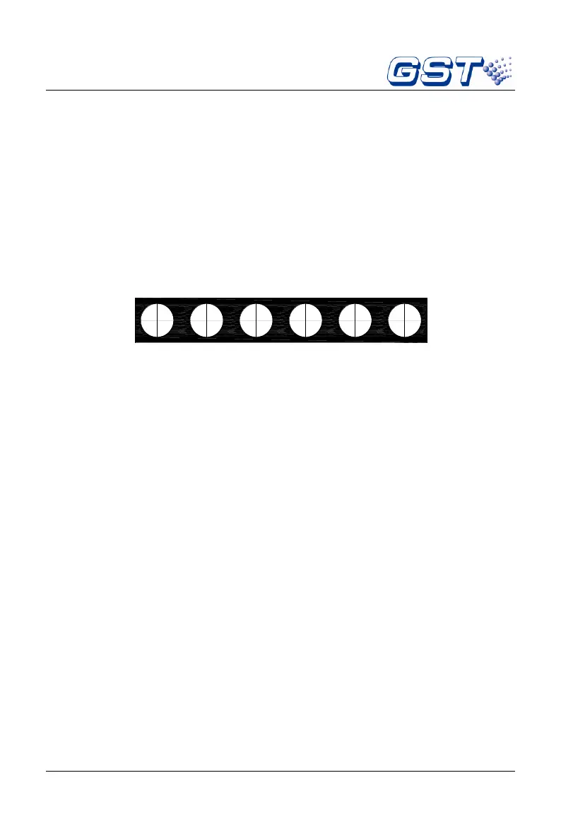
d) Recommended Wiring
In field, D1, D2 (polarity insensitive) of a detector should be
connected to 24VDC power line. The reflector doesn’t need any
wires. K11 and K12 are fire output contacts. K21and K22 are
fault output contacts. The terminals of the detector are shown in
Fig.12.
Fig.12
Wiring: 1.5mm
2
or above fire cable for D1, D2. 1.0mm
2
or above
twisted pair for K11, K12, K21 and K22. 1.0mm
2
or above for the grounding
wire.
Note: As the detector is mounted in the special environment
such as dust, damp, three positions as shown in Fig. 2 should be
sealed with glass glue or 703 silica gel after fixing and wiring,
ensuring the detector works stably.
6. Commissioning
1) Commissioning Steps
a) Protective film of the detector and the reflector should be removed
without scratching their surfaces.
Take off the top cover of the detector, and then switch on the power of
the detector. After two minutes, make the Magnet
○
M of a
commission tool approach the reed switch (near the Fire LED)
located on the interface board of the detector. At the moment, the