11
In the following section, the Photo Eye Safety System and
Push Button will be connected to the Opener. Please read
and understand the wiring instructions before connecting
wires.
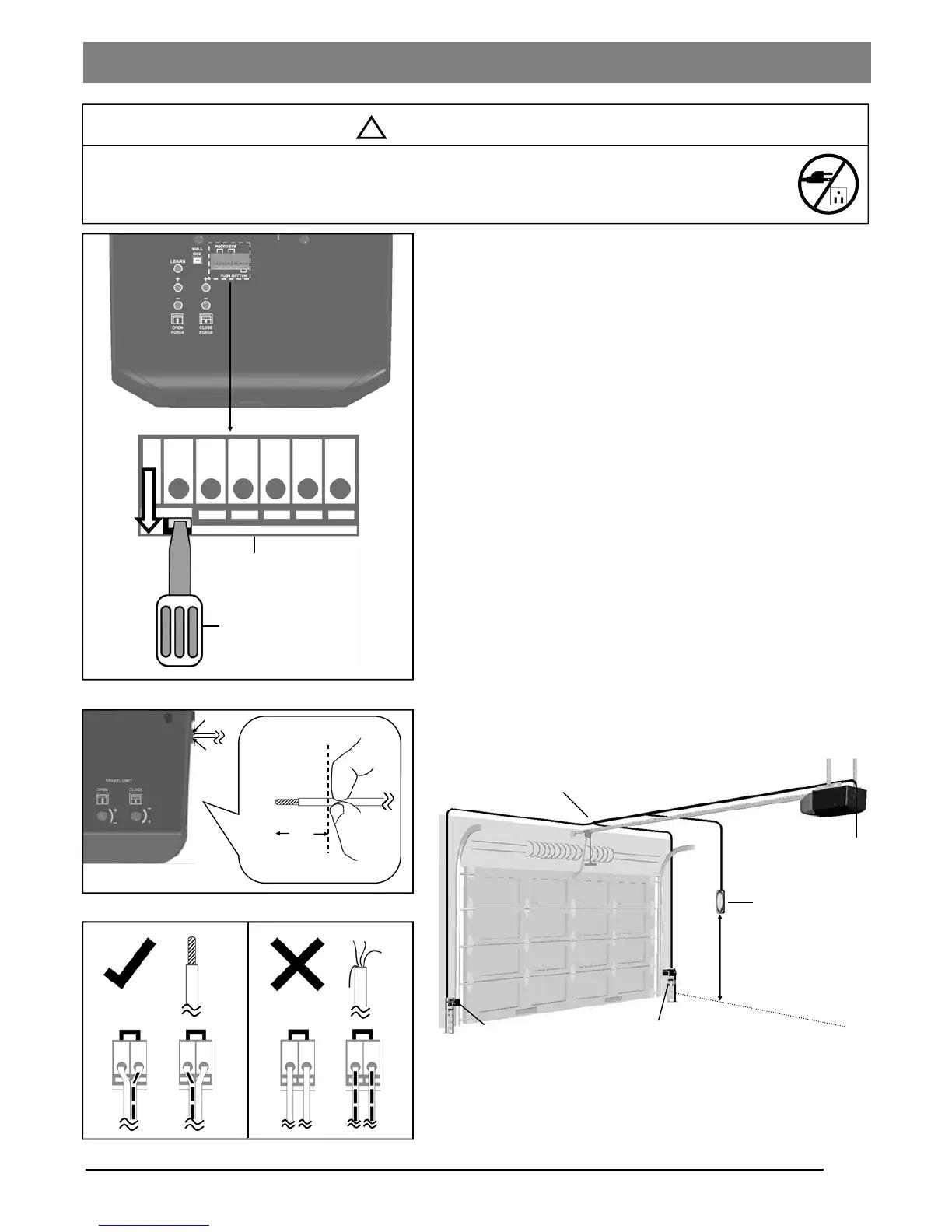
1. The connection terminals on the rear panel of the Opener
are used to connect wires from accessories.
2. To connect a wire to an assigned terminal, use a small “flat
head” screwdriver to push in the orange tab on the Wire
Terminal as shown in Fig.1.
3. Insert approximately 1/2” (13mm) of the wire into the
terminal while pushing in the tab as shown in Fig.2.
4. Wires MUST NOT be frayed and connected properly as
shown in Fig.3. Each accessory requires a pair of
terminals, Each pair of terminals MUST be connected with
one white wire and one striped wire (non-polarized) from
the SAME accessory.
5. Check for proper connection by gently pulling on the wire.
The wire should not come out of the terminal. NO exposed
part of the wire should be visible outside of the terminal.
6. Use the insulated staples provided to secure the wires to
the wall and/or ceiling. Be careful not to damage the wires
while securing the staples.
Fig. 1
To prevent SERIOUS INJURY or DEATH from electrocution:
- Power MUST NOT be connected until instructed.
- NO exposed part of the wire should be visible outside of the terminal for proper connection.
Screwdriver or similar tool
Push Button
Photo Eye Safety System
Wires to the terminals on the Opener
Min. 5 feet (1.5m)
above floor
Terminals
Wire Terminals
Open
Wiring Instructions
Fig. 2
Fig. 3
Insert into unit
Outside
Wire shown in actual size
1/2”
!
WARNING