Section 5
ENGINE DC CONTROL SYSTEM
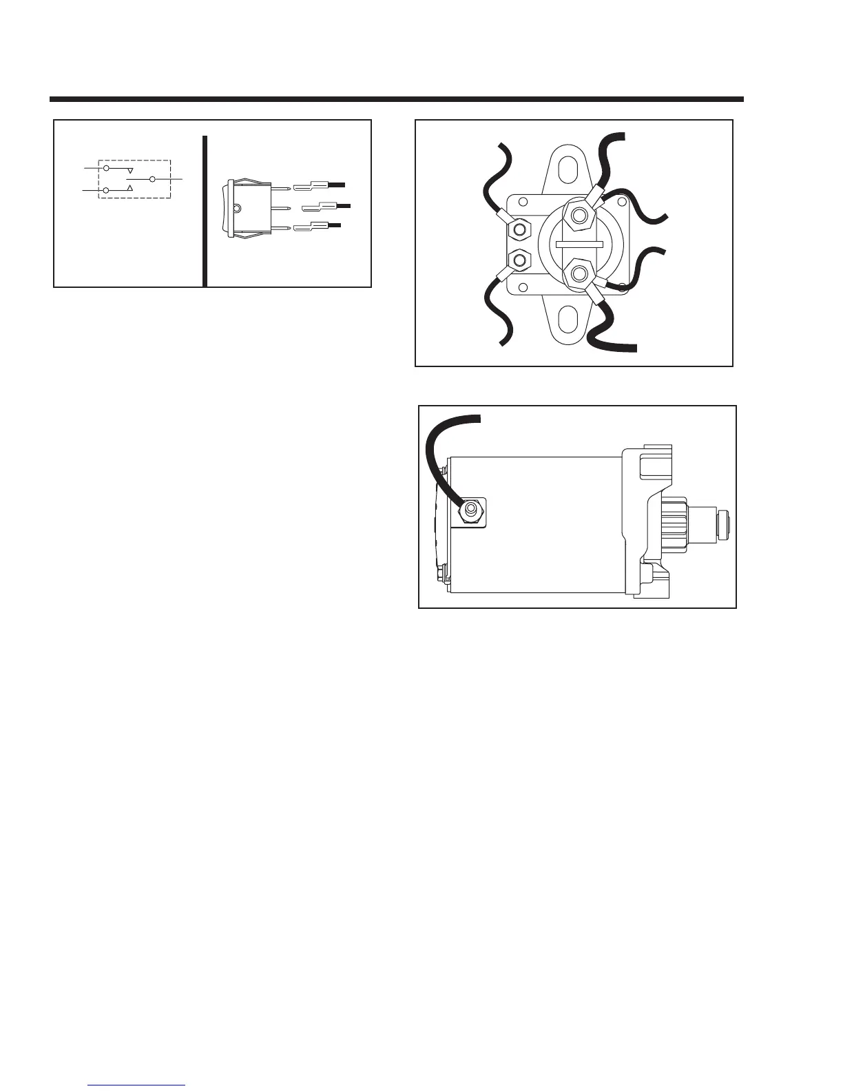
Figure 5-5. – Start-Stop Switch
STARTER CONTACTOR & MOTOR
The positive (+) battery cable (13) attaches to one of
the large lugs of the Contactor along with Wire 13 for
DC supply to the Fuse (F1). The Starter cable (16)
attaches to the second large lug, along with Wire 16
for the Field Boost Circuit. Attached to the two small
lugs are Wires 56 and 0.
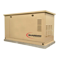
When the Start-Stop switch is set to "START", the cir-
cuit board delivers battery voltage to the Contactor
coil via Wire 56. The Contactor energizes and its con-
tacts close. Battery voltage is then delivered from the
positive battery cable, across the closed contacts and
to the Starter Motor via Wire 16.
Figure 5-6. – Starter Contactor
Figure 5-7. – Starter Motor
A. Schematic
B. Pictorial