Section 7
DIAGNOSTIC TESTS
PROCEDURE:
1. Set VOM to measure DC voltage.
2. Disconnect Wire No. 4 from the Voltage Regulator and connect
the positive (+) test lead to it. Connect the negative (-) test lead
to a clean frame ground.
3. Set the Start-Stop switch to “Start.” During cranking only, mea-
sure DC voltage. It should read 3-5 VDC. Reconnect Wire No.
4 to the Voltage Regulator. If voltage is measured, it can be
assumed that the Field Boost is working. Stop testing. If volt-
age is not measured, proceed to Step 4.
4. Connect the positive (+) test lead to Wire No. 16 at pin location
J1-13 on the PCB (see Figure 7-4) (J1, J2 & J3 connectors
remain connected to PCB). Connect the negative(-) test lead to
a clean frame ground.
5. Set the Start-Stop switch to “Start.” During cranking only, bat-
tery voltage should measure 11-12 VDC.
6. Connect the positive (+) test lead to Wire No. 4 at pin location
J1-9 on the PCB (see Figure 7-4) (J1, J2 & J3 connectors
remain connected to PCB). Connect the negative(-) test lead to
a clean frame ground.
7. Set the Start-Stop switch to “Start.” During cranking only mea-
sure the DC voltage. It should measure 3-5 VDC.
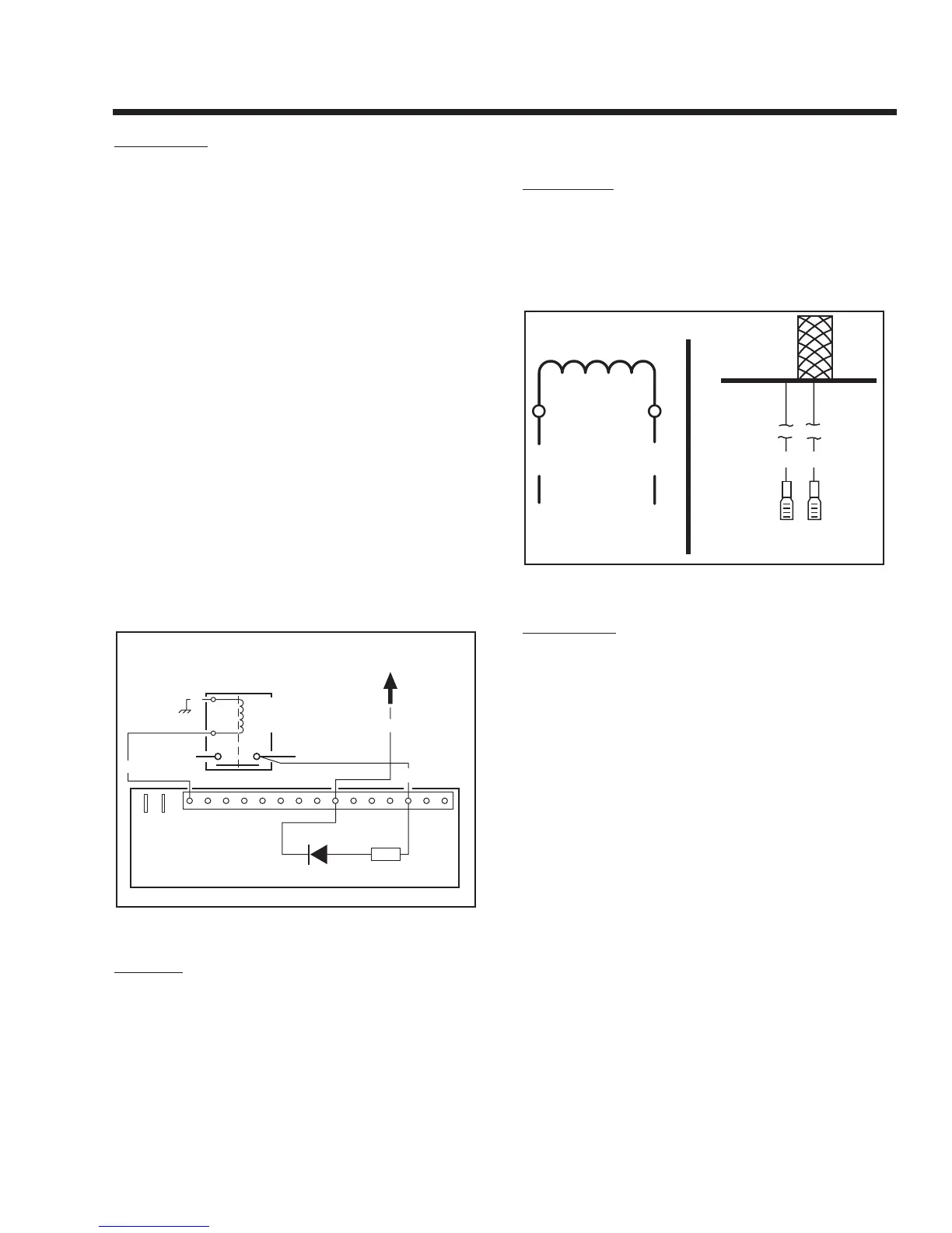
Figure 7-4. – The Field Boost Circuit
RESULTS:
1. If battery voltage was not measured in Step 5, repair or replace
Wire No. 16 between the Starter Contactor and PCB.
2. If field boost voltage was measured in Step 7 but not measured
in Step 3, repair or replace Wire No. 4 between PCB and
Voltage Regulator.
3. If battery voltage was measured in Step 5 but field boost volt-
age was not measured in Step 7, replace PCB.
TEST 7 - TEST STATOR DPE WINDING
DISCUSSION:
An open circuit in the Stator excitation windings will
result in a loss of unregulated excitation current to the
Voltage Regulator. The flow of regulated excitation cur-
rent to the Rotor will then terminate and the unit's AC
output voltage will drop to a value that is commensurate
with the rotor’s residual magnetism (about 5 - 12 VAC).
Figure 7-5. – Stator Excitation Winding
PROCEDURE:
1. Disconnect Wire No. 2 from the excitation circuit breaker.
2. Disconnect Wire No. 6 from the Voltage Regulator.
3. Set a VOM to its "Rx1" scale and zero the meter.
4. Connect the VOM test leads across the terminal ends of Wires
No. 2 and 6. The VOM should indicate the resistance of the
Stator excitation (DPE) windings.
NOMINAL RESISTANCE OF
STATOR EXCITATION “DPE” WINDINGS*
2.168 - 2.510 OHMS
* Resistance values In ohms at 20° C. (68° F.). Actual readings
may vary depending on ambient temperature. A tolerance of
plus or minus 5% is allowed.
5. Now, set the meter to its "Rx1 K" or "Rx10,000" scale and zero
the meter. Test for a "short-to-ground" condition as follows:
a.Connect one meter test lead to Stator lead No.
2, the other test lead to a clean frame ground.
b.The meter should read "infinity". Any other read-
ing indicates a "short-to-ground" condition and
the Stator should be replaced.
6. Test for a short between windings as follows:
a.Meter should be set to its "Rx1 K" or "Rx10,000"
scale.
A.
B. Pictoria