Section 7
DIAGNOSTIC TESTS
ground. Battery voltage should be measured. Verify that Wire
No. 15 is connected to J3 and that Wire No. 14 is connected to
J2; if reversed the unit will produce no spark.
4. Set the VOM to measure resistance. Connect the negative (-)
test lead to Wire No. 18A, which goes to the coil. Connect the
positive (+) test lead to frame ground. Approximately 1.5 k
Ω
should be measured.
5. Set the VOM to measure resistance. Disconnect the high ten-
sion lead from the spark plug. Connect one test lead to the
high tension lead. Connect the other test lead to frame ground.
Approximately 16 k
Ω
should be measured.
RESULTS:
1. If infinity is not measured in Step 2, repair or replace grounded
Wire No. 18 between ECB and bullet connector.
2. If battery voltage is not measured in Step 3, reconnect Wire
No. 15 and Wire No. 14 to the correct terminal locations.
3. If the Ignition Coil fails Step 4 or Step 5 by a high margin,
replace the Ignition Coil.
4. If the coil passes Step 4 and Step 5, but there is still no spark,
replace the Ignition Coil.
Note: Before replacing the Ignition Coil, check the
Flywheel Magnet.
CHECKING FLYWHEEL MAGNET:
The flywheel magnet rarely loses its magnetism. If
you suspect a magnet might be defective, a rough
test can be performed as follows:
1. Place the flywheel on a wooden surface.
2. Hold a screwdriver at the extreme end of its handle and with its
point down.
3. Move the tip of the screwdriver to about 3/4 inch (19mm) from
the magnet. The screwdriver blade should be pulled in against
the magnet.
FLYWHEEL KEY:
In all cases, the flywheel’s taper is locked on the
crankshaft taper by the torque of the flywheel nut. A
keyway is provided for alignment only and theoretical-
ly carries no load.
If the flywheel key becomes sheared or even partially
sheared, ignition timing can change. Incorrect timing
can result in hard starting or failure to start.
TEST 35 - CHECK VALVE ADJUSTMENT
DISCUSSION:
The valve lash must be adjusted correctly in order to pro-
vide the proper air/fuel mixture to the combustion chamber.
ADJUSTING VALVE CLEARANCE:
Adjust valve clearance with the engine at room tem-
perature. The piston should be at top dead center
(TDC) of its compression stroke (both valves closed).
An alternative method is to turn the engine over and
position the intake valve fully open (intake valve
spring compressed) and adjust the exhaust valve
clearance. Turn the engine over and position the
exhaust valve fully open (exhaust valve spring com-
pressed) and adjust the intake valve clearance.
Correct valve clearance is given below, in INCHES
(MILLIMETERS).
Intake Valve 0.001-0.0022 (0.03-0.056)
Exhaust Valve 0.0018-0.003 (0.046-0.07)
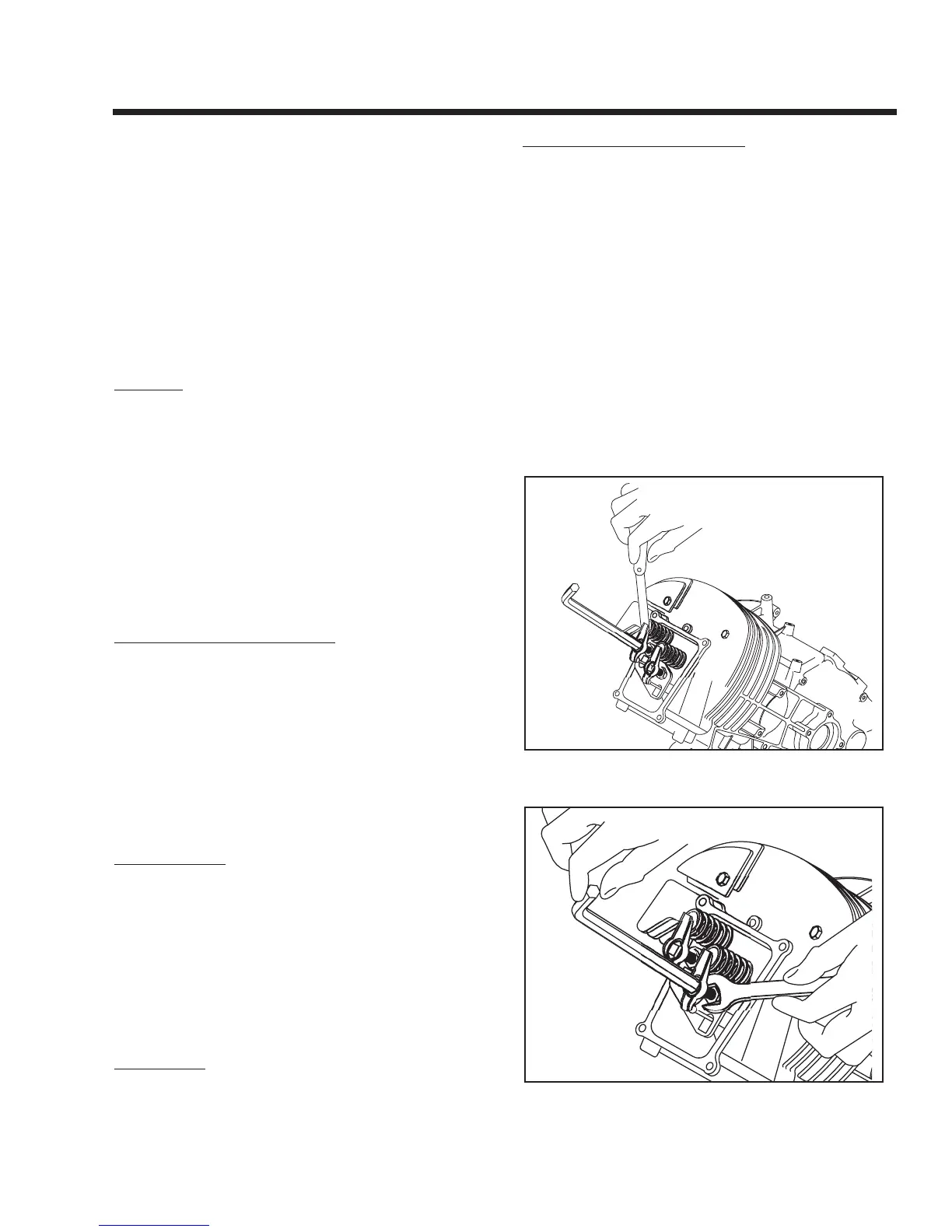
1. Loosen the rocker arm jam nut. Use an 8mm allen wrench to turn
the pivot ball stud while checking the clearance between the
rocker arm and valve stem with a feeler gauge (see Figure 7-27).
Figure 7-27 – Adjusting Valve Clearance
Figure 7-28 – Tightening the Jam Nut
Page 47