Section 7
DIAGNOSTIC TESTS
fuel primer switch. This will activate the fuel pump and fuel
solenoid. The fuel solenoid should energize and you should be
able to feel and hear it. If the Fuel Solenoid does not operate,
proceed to Step 4.
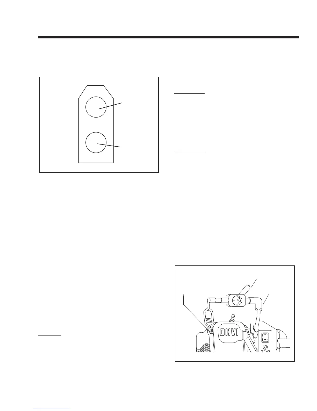
Figure 7-22. – Connector 3, Fuel Solenoid to Panel
4. Set the VOM to measure DC voltage. Disconnect Connector 3
from the Fuel Solenoid. Connect the positive (+) meter test
lead to Wire No. 14 (Connector 3, Pin 2) that goes to the con-
trol panel.Connect the other test lead to a clean frame ground.
Set the Start-Stop Switch to “START.” Battery voltage should
be measured.
5. Set the VOM to measure resistance. Disconnect Connector 3
from the Fuel Solenoid. Connect one test lead to Wire No. 0
(Connector 3, Pin 1) that goes to the control panel. Connect
the other test lead to a clean frame ground. Continuity should
be measured.
Short to Ground:
6. Set the VOM to measure resistance. Disconnect Connector to
the Fuel Solenoid. Connect one meter test lead to one pin on
the Fuel Solenoid. Connect the other meter test lead to the
Fuel Solenoid housing. Infinity should be measured. If continu-
ity is measured, a short to ground exists. (Fuel Solenoid coil
resistance is approximately 30.1 ohms. Current draw of the
Fuel Solenoid at nominal voltage is approximately 418 mil-
liamps or 0.418 amps).
RESULTS:
1. If the Fuel Solenoid passes Steps 4 & 5 but does NOT operate
in Step 3, replace or repair Fuel Solenoid.
2. If battery voltage is not measured in Step 4, repair or replace
Wire No. 14 between Connector 3 and the 4-tab terminal.
3. If continuity is not measured in Step 5, repair or replace Wire
No. 0 between the Fuel Solenoid and ground terminal.
4. If the Fuel Solenoid operates, proceed to Test 32.
TEST 32 - CHECK IGNITION SPARK
DISCUSSION:
A problem in the engine Ignition system can cause
any of the following:
• Engine will not start.
• Engine starts hard, runs rough.
A commercially available spark tester may be used to
test the engine ignition system. One can also be pur-
chased from Generac Power Systems (Part No.
0C5969).
PROCEDURE:
1. Disconnect the high tension lead from the spark plug.
2. Attach the high tension lead to the spark tester terminal.
3. Ground the spark tester clamp by attaching to the cylinder
head.
4. Crank the engine rapidly. Engine must be cranking at 350 rpm
or more. If spark jumps the tester gap, you may assume the
ignition system is working properly.
5. To determine if an engine miss is ignition related, connect the
spark tester in series with the high tension lead and the spark
plug. Then, start the engine. If spark jumps the tester gap at
regular Intervals, but the engine miss continues, the problem
may be in the spark plug or fuel system. Proceed to Test 33.
6. If spark jumps the tester gap intermittently, the problem may be
in the Ignition Coil. Proceed to Test 34.
Figure 7-23. – Testing Ignition System