INSTALLATION
14
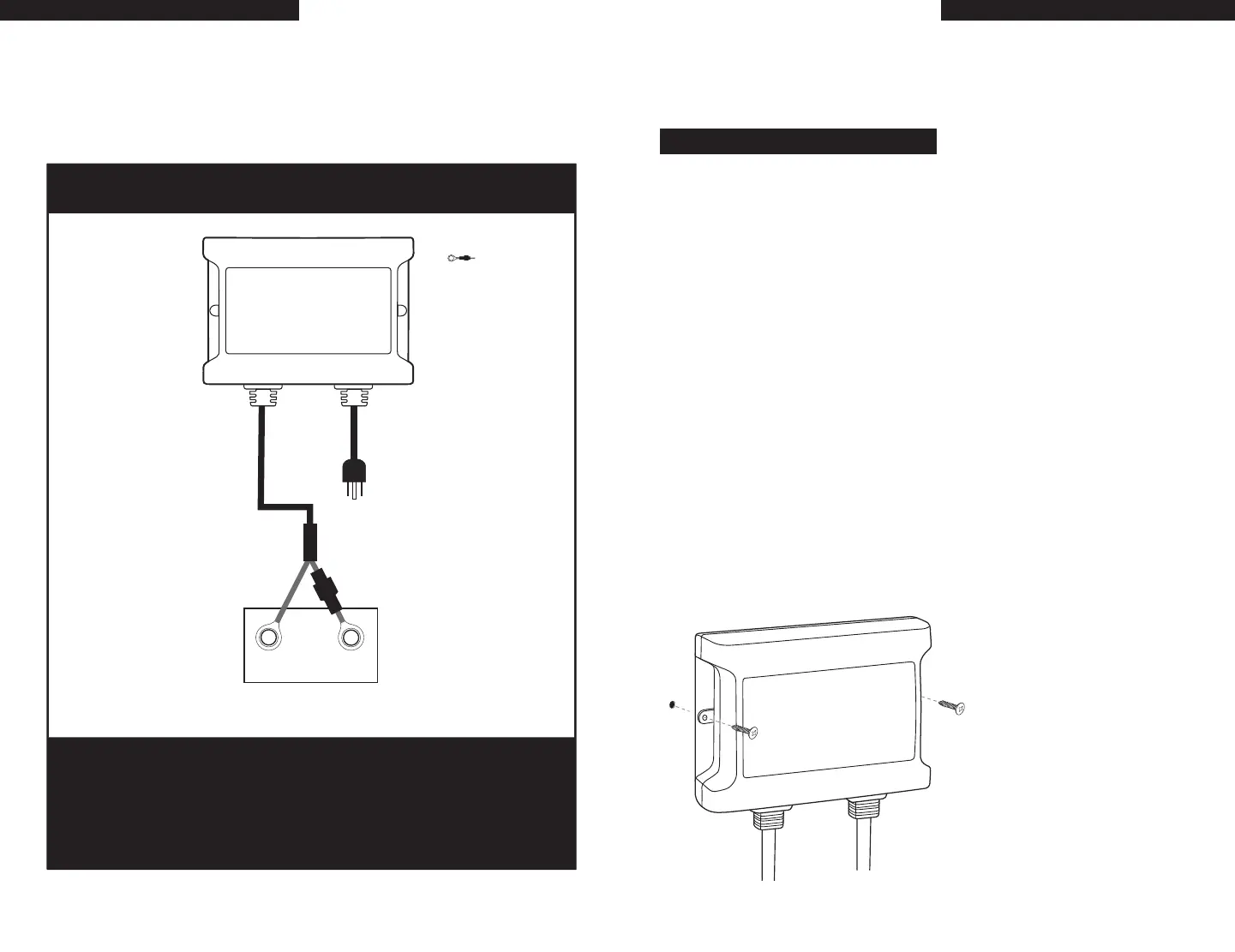
WIRING DIAGRAMS
13
Ignition Protected On-Board Installed Applications
When connecting each jacketed battery charger cable, make sure it is connected
to only
one 12 VDC battery
and observe the polarity and color of all connections:
Red Wire = + (Positive) Battery connection
Black Wire =
-
(Negative) Battery connection
The black wire can never be connected to a terminal with red wires. Only black.
Installation
Ring Terminal Cable Installation for Mounting the ChargePro
™
1.5 On-Board
a Boat or Under a Hood Requiring Ignition Protected Installation.
Note:
Indicates fuse
12 Volt Engine Battery
Top view
of battery
For Ignition Protected Applications On-Board Installation with Ring
Terminal Cable Assembly Only
The ChargePro
™
1.5 Dual Use Maintainer and Charger can be permanently mounted on-board,
and can be mounted vertically or horizontally. (vertically is recommended for LED viewing)
Only use the ring terminal cable assembly for on-board and ignition protected
applications.
Always mount your ChargePro
™
1.5 in a compartment area that can be properly ventilated
during use.
Do NOT make any electrical connections to the
ChargePro
™
1.5 or batteries until the following
steps are completed:
10 Easy to follow installation steps (after removing mounting hole covers):
1. Select a mounting location that allows for free air ventilation with a minimum of 4 inches of clear
unobstructed space around and in front of the
ChargePro
™
1.5. Open all battery and engine
compartments and ventilate for at least 15 minutes before starting the installation of the
ChargePro
™
1.5.
2. Confirm the DC battery cable can reach the battery for proper connections. Confirm the LEDs
are viewable.
3. Using the ChargePro
™
1.5 as a mounting template, use a small awl or screwdriver to
mark the position of each mounting hole or tape the template in the mounting area
to drill the pilot holes.
4. Using a 1/8" drill bit, drill pilot holes in the (2) marked locations as described in step 3.
Apply a silicon sealer in each of the mounting locations to waterproof the screw holes.
5. Position the ChargePro
™
1.5 over the mounting holes and secure with a power screwdriver
by installing 2 marine grade or #6 x 1” stainless steel screws. (mounting screws not included)
1/8" pilot hole
with silicon sealer
IMPORTANT NOTICE
Confirm the surface you will be
mounting the ChargePro
™
1.5 to
is adequate in strength and
thickness to hold the ChargePro
™
1.5 in place with the mounting
screws you have selected.
red
black
+
_
bat 1
ChargePro
™
1.5 Amp
Dual Use Maintainer
and Charger
Ring terminal cable assembly

 Loading...