6
© Guldmann GB/US-1996/09/2016 • # 554400_3
© Guldmann GB/US-1996/09/2016 • # 554400_3
4.00 Unpacking and preparation of the lifter
Visual check of lifter
If the packaging is damaged on receipt, each part of the lifter must be careful-
ly examined for visible defects or deciencies. In case of suspected damage,
do not use the lifter until authorized by qualied service staff or the Guldmann
Service Team.
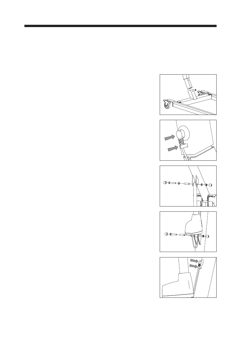
Assembling mast/chassis – electrical
Loosen screw tted to mast. Position the mast
in the base. When mast is in as far as it will
go, tighten screw using an M5 Allen key. To
dismantle, remove screw to pull mast out of
base. Retighten screw in mast.
Mounting of connectors for motors and
hand control
Fit connectors for width adjustment motor in
the mast and hand control in the control box.
Fitting actuator
Fasten the actuator using the attached bush-
ing and screw with nut.
Tighten screw and nut with a 17 mm spanners,
and put on the nut protector.
Bush and bolt for top of lifting actuator
L1 = 55 mm
L2 = 42 mm
Bush and bolt for bottom of lifting actuator
L3 = 50 mm
L4 = 39 mm
L1 L2
L3 L4