8
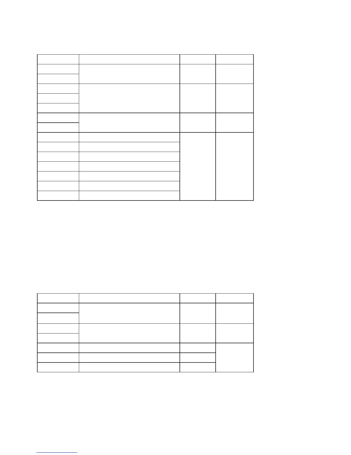
Terminal Description Voltage Max current
L1 Auxiliary Live terminals for powering external
devices
230V AC 3A
L2
L Mains power supply input, power this from a
5A fused spur
230V AC 5A
N
E
N1 Auxiliary Neutral terminals for powering
external devices
230V AC 3A
N2
R1NO Relay 1 normally open terminal Up to 230V
AC or up to
24V DC
3A (AC or DC)
R1NC Relay 1 normally closed terminal
R1C Relay 1 common terminal
R2NO Relay 2 normally open terminal
R2C Relay 2 common terminal
R3NO Relay 3 normally open terminal
R3C Relay 3 common terminal
Table 2. Mains Terminals Specification
Signal Compartment
All cables entering this compartment must have an external
diameter between 4 and 6mm for compatibility with the strain
relief system. All cables must be less than 3m in length for EMC
compliance.
Terminal Description Voltage Max current
PULSE Pulse input, for connecting a voltage-free
(“dry contact”) switching device such as a
meter’s pulse output
3.6V DC 12mA
PULSE
MBUS- M-Bus master node for connecting up to five
M-Bus slave devices
36V DC 400 mA
MBUS+
A5V Analogue 5V reference 5V DC 20 mA
Ain Analogue voltage input 0 – 5V DC
A0V Analogue 0V 0V
Table 3. Signal Terminals Specification
 Loading...