Model H-2000/H-3500 Proportioning Unit
16 159421A-1, Issue 2
7.
Connect the heated hose assemblies.
NOTE:
The hoses are Connected end to
end during shipment to protect
them from moisture intrusion. Do
not separate the hoses until they
are ready to couple to the
proportioning unit.
Important: The importance of making proper hose connections cannot be overly
emphasized. The connection points are a potential source of chemical and air leaks
and are the points, most exposed to damage from scuffing and snagging on abrasive
surfaces. A liberal amount of duct tape can be used in this area to make the bundle as
compact as possible. Gusmer strongly recommends installing the optional scuff jacket
to protect the hose insulation and TSU extension from damage. A proper hose
connection is shown in sequence on the following page
The key areas of extra attention during installation are as follows:
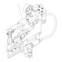
a)
DO NOT interchange the
hoses: Resin hoses are
color coded BLUE,
Isocyanate hoses are color
coded RED.
Figure 7. Hose Connection Step (a)
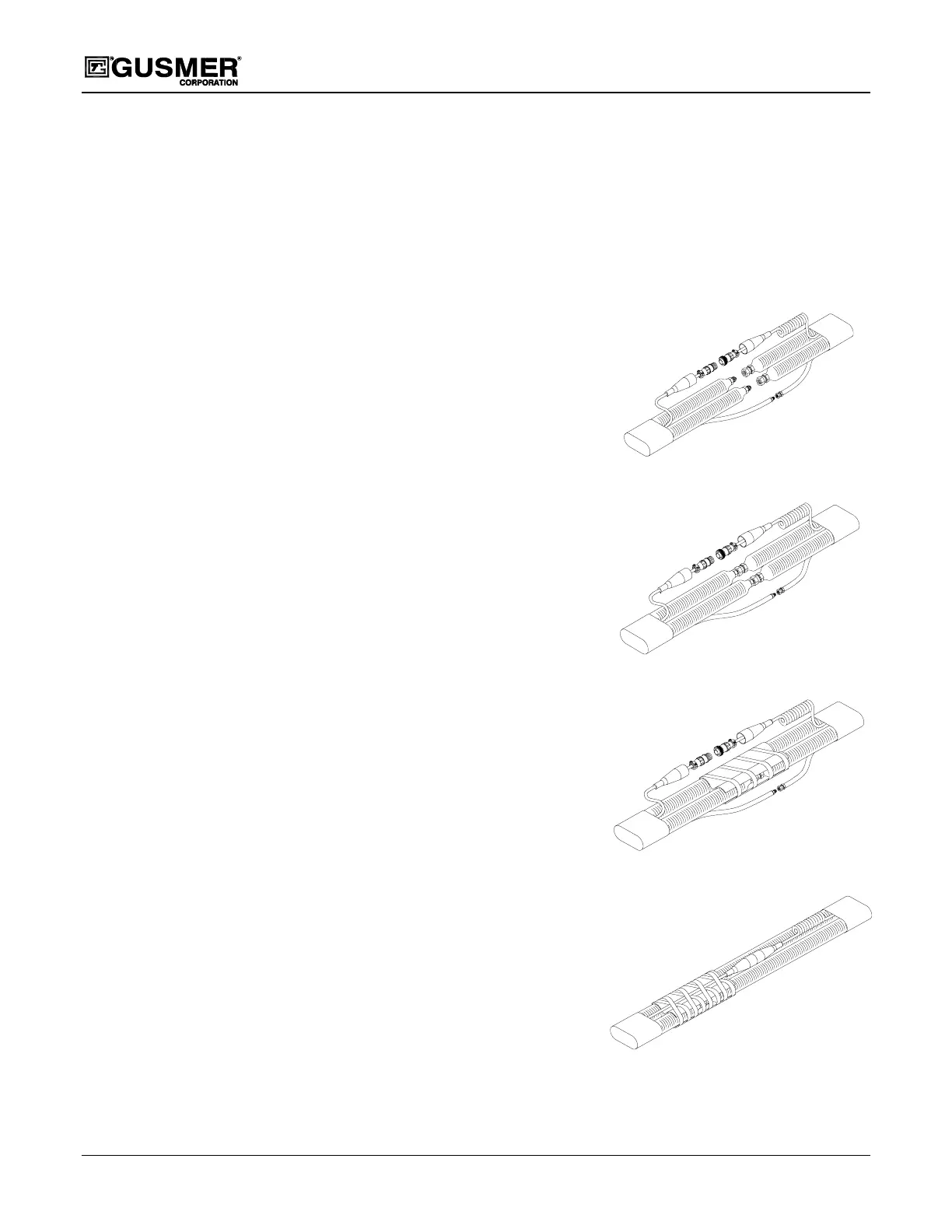
b)
To assure a leak proof
chemical connections,
take care not to cross
thread the fitting and DO
NOT over-tighten.
Figure 8. Hose Connection Step (b)
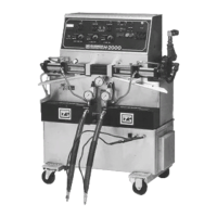
c)
Tape the electrical
isolator securely in place
between the hydraulic
fittings: failure to do so
will cause a short circuit
in the hose heating
system.
Figure 9. Hose Connection Step (c)
d)
To assure a secure
electrical connection:
place the protective
electrical isolator boot
over each plug and tape
together.
Figure 10. Hose Connection Step (d)
*** Repeat Step 7 for adding additional hoses. ***