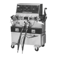
Model H-2000/H-3500 Proportioning Unit
28 159421A-1, Issue 2
S
OLUTIONS
1.
A completely independent, over-temperature, safety circuit has been provided and
consists of four (4) thermal limit safety switches attached to the heating tube(s).
When the surface temperature of the tube(s) exceeds 230° F, the thermal limit safety
switch will automatically trip the primary heater circuit breaker to OFF. The
temperature of the Primary Heater must cool down to within limits before you can
reset the circuit breaker. DO NOT attempt to reset the circuit breaker more than
once. You must determine the cause of the problem and correct it.
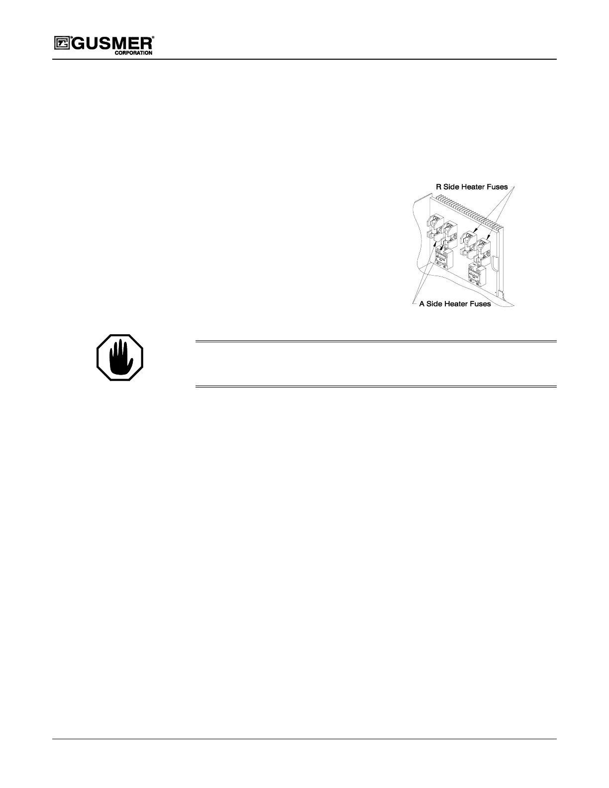
2.
PRIMARY HEATER FUSE-the
primary heating circuit is protected by
two 30 Amp fuses. With power OFF,
remove the fuse(s) and check it for
continuity or simply replace it with one
known to be good.
Figure 22. Primary Heater Fuses
WARNING:
T
HE FUSE MUST BE REPLACED WITH ONE OF THE SAME RATING
. A
SUBSTITUTE
MAY DAMAGE THE EQUIPMENT AND WOULD CREATE A POTENTIAL SOURCE OF INJURY TO THE
OPERATOR
.
3.
PRIMARY HEATER SSR
With Main Power OFF, remove the lead from terminal #1 on the SSR. Check for
continuity across terminals #1 and #2. If continuity is present, the SSR has shorted
closed and needs replacing. (Refer to Figure 17).
It is not possible to check for normal operation of the SSR without electric power.
Therefore, if all other testing fails to determine the source of the problem, assume the
SSR is inoperative and replace it.
Important: For the SSR to operate properly the heat generated by it must be passed
off to the heat sink and dissipated. DO NOT obstruct the heat sink with rags,
polyethylene, or other protective covering, or locate the unit in close proximity to a
wall. Always allow for as much air circulation as possible, since the effectiveness of
the heat sink is dependent upon unobstructed airflow.
4.
PRIMARY HEATER CONTROL UNIT- the three heat controller units on the H-
2000/H-3500 are directly interchangeable with one another. To determine if a
control unit is operating correctly, with the power OFF, replace the suspected
controller with one known to be good.
5.
THERMOCOUPLE- the design of the temperature controller units includes a fail-
safe feature, which prevents the heating system from operating in the event that there
is no signal from the thermocouple. In this case, the thermocouple requires
replacing. Refer to the Maintenance section of this manual for the proper procedures.
6.
HEATING ELEMENTS- the heater contains four 1500-Watt (32-ohm) heating
elements wired in parallel. To check operation of the elements proceed as follows:
 Loading...